
Page 38 -
P. 38
Section 1.1 Image Formation 6
Π j
d P
k
c O
p
i
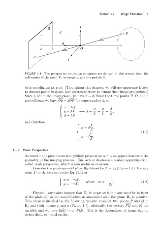
FIGURE 1.4: The perspective projection equations are derived in this section from the
collinearity of the point P, its image p, and the pinhole O.
with coordinates (x, y, z). (Throughout this chapter, we will use uppercase letters
to denotes points in space, and lowercase letters to denote their image projections.)
Since p lies in the image plane, we have z = d. Since the three points P, O,and p
−→ −−→
are collinear, we have Op = λOP for some number λ,so
⎧
⎨ x = λX x y d
y = λY ⇐⇒ λ = = = ,
d = λZ
⎩ X Y Z
and therefore
⎧
X
⎪ x = d ,
⎪
Z
⎨
(1.1)
Y
⎩ y = d .
⎪
⎪
Z
1.1.2 Weak Perspective
As noted in the previous section, pinhole perspective is only an approximation of the
geometry of the imaging process. This section discusses a coarser approximation,
called weak perspective, which is also useful on occasion.
Consider the fronto-parallel plane Π 0 defined by Z = Z 0 (Figure 1.5). For any
point P in Π 0 we can rewrite Eq. (1.1) as
x = −mX, d
where m = − . (1.2)
y = −mY, Z 0
Physical constraints impose that Z 0 be negative (the plane must be in front
of the pinhole), so the magnification m associated with the plane Π 0 is positive.
This name is justified by the following remark: consider two points P and Q in
−−→ − →
Π 0 and their images p and q (Figure 1.5); obviously, the vectors PQ and pq are
−−→
− →
parallel, and we have ||pq|| = m||PQ||. This is the dependence of image size on
object distance noted earlier.