
Page 235 -
P. 235
214 4 Feature detection and matching
(a) (b) (c)
(d) (e) (f)
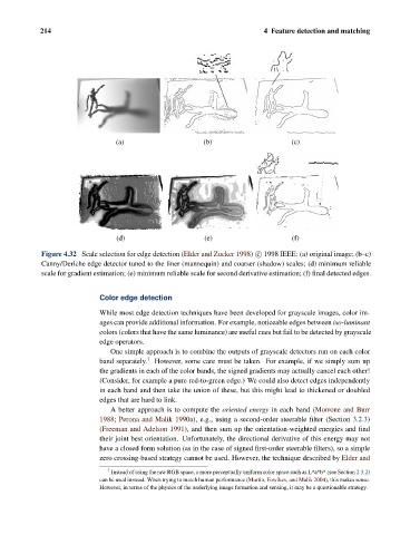
Figure 4.32 Scale selection for edge detection (Elder and Zucker 1998) c 1998 IEEE: (a) original image; (b–c)
Canny/Deriche edge detector tuned to the finer (mannequin) and coarser (shadow) scales; (d) minimum reliable
scale for gradient estimation; (e) minimum reliable scale for second derivative estimation; (f) final detected edges.
Color edge detection
While most edge detection techniques have been developed for grayscale images, color im-
ages can provide additional information. For example, noticeable edges between iso-luminant
colors (colors that have the same luminance) are useful cues but fail to be detected by grayscale
edge operators.
One simple approach is to combine the outputs of grayscale detectors run on each color
band separately. 7 However, some care must be taken. For example, if we simply sum up
the gradients in each of the color bands, the signed gradients may actually cancel each other!
(Consider, for example a pure red-to-green edge.) We could also detect edges independently
in each band and then take the union of these, but this might lead to thickened or doubled
edges that are hard to link.
A better approach is to compute the oriented energy in each band (Morrone and Burr
1988; Perona and Malik 1990a), e.g., using a second-order steerable filter (Section 3.2.3)
(Freeman and Adelson 1991), and then sum up the orientation-weighted energies and find
their joint best orientation. Unfortunately, the directional derivative of this energy may not
have a closed form solution (as in the case of signed first-order steerable filters), so a simple
zero crossing-based strategy cannot be used. However, the technique described by Elder and
7
Instead of using the raw RGB space, a more perceptually uniform color space such as L*a*b* (see Section 2.3.2)
can be used instead. When trying to match human performance (Martin, Fowlkes, and Malik 2004), this makes sense.
However, in terms of the physics of the underlying image formation and sensing, it may be a questionable strategy.