
Page 97 -
P. 97
76 2 Image formation
G R G R rGb Rgb rGb Rgb
B G B G rgB rGb rgB rGb
G R G R rGb Rgb rGb Rgb
B G B G rgB rGb rgB rGb
(a) (b)
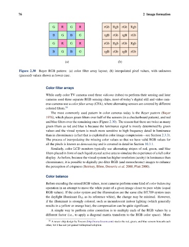
Figure 2.30 Bayer RGB pattern: (a) color filter array layout; (b) interpolated pixel values, with unknown
(guessed) values shown as lower case.
Color filter arrays
While early color TV cameras used three vidicons (tubes) to perform their sensing and later
cameras used three separate RGB sensing chips, most of today’s digital still and video cam-
eras cameras use a color filter array (CFA), where alternating sensors are covered by different
colored filters. 20
The most commonly used pattern in color cameras today is the Bayer pattern (Bayer
1976), which places green filters over half of the sensors (in a checkerboard pattern), and red
and blue filters over the remaining ones (Figure 2.30). The reason that there are twice as many
green filters as red and blue is because the luminance signal is mostly determined by green
values and the visual system is much more sensitive to high frequency detail in luminance
than in chrominance (a fact that is exploited in color image compression—see Section 2.3.3).
The process of interpolating the missing color values so that we have valid RGB values for
all the pixels is known as demosaicing and is covered in detail in Section 10.3.1.
Similarly, color LCD monitors typically use alternating stripes of red, green, and blue
filters placed in front of each liquid crystal active area to simulate the experience of a full color
display. As before, because the visual system has higher resolution (acuity) in luminance than
chrominance, it is possible to digitally pre-filter RGB (and monochrome) images to enhance
the perception of crispness (Betrisey, Blinn, Dresevic et al. 2000; Platt 2000).
Color balance
Before encoding the sensed RGB values, most cameras perform some kind of color balancing
operation in an attempt to move the white point of a given image closer to pure white (equal
RGB values). If the color system and the illumination are the same (the BT.709 system uses
the daylight illuminant D 65 as its reference white), the change may be minimal. However,
if the illuminant is strongly colored, such as incandescent indoor lighting (which generally
results in a yellow or orange hue), the compensation can be quite significant.
A simple way to perform color correction is to multiply each of the RGB values by a
different factor (i.e., to apply a diagonal matrix transform to the RGB color space). More
20 A newer chip design by Foveon (http://www.foveon.com) stacks the red, green, and blue sensors beneath each
other, but it has not yet gained widespread adoption.