
Page 123 - Concise Encyclopedia of Robotics
P. 123
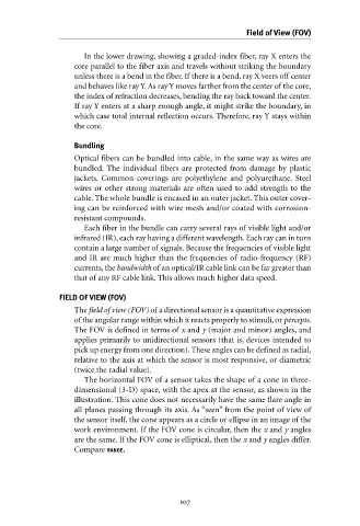
In the lower drawing, showing a graded-index fiber, ray X enters the
core parallel to the fiber axis and travels without striking the boundary
unless there is a bend in the fiber. If there is a bend, ray X veers off center
and behaves like ray Y. As ray Y moves farther from the center of the core,
the index of refraction decreases, bending the ray back toward the center.
If ray Y enters at a sharp enough angle, it might strike the boundary, in
which case total internal reflection occurs. Therefore, ray Y stays within
the core.
Bundling Field of View (FOV)
Optical fibers can be bundled into cable, in the same way as wires are
bundled. The individual fibers are protected from damage by plastic
jackets. Common coverings are polyethylene and polyurethane. Steel
wires or other strong materials are often used to add strength to the
cable. The whole bundle is encased in an outer jacket. This outer cover-
ing can be reinforced with wire mesh and/or coated with corrosion-
resistant compounds.
Each fiber in the bundle can carry several rays of visible light and/or
infrared (IR), each ray having a different wavelength. Each ray can in turn
contain a large number of signals. Because the frequencies of visible light
and IR are much higher than the frequencies of radio-frequency (RF)
currents, the bandwidth of an optical/IR cable link can be far greater than
that of any RF cable link. This allows much higher data speed.
FIELD OF VIEW (FOV)
The field of view (FOV) of a directional sensor is a quantitative expression
of the angular range within which it reacts properly to stimuli, or percepts.
The FOV is defined in terms of x and y (major and minor) angles, and
applies primarily to unidirectional sensors (that is, devices intended to
pick up energy from one direction). These angles can be defined as radial,
relative to the axis at which the sensor is most responsive, or diametric
(twice the radial value).
The horizontal FOV of a sensor takes the shape of a cone in three-
dimensional (3-D) space, with the apex at the sensor, as shown in the
illustration. This cone does not necessarily have the same flare angle in
all planes passing through its axis. As “seen” from the point of view of
the sensor itself, the cone appears as a circle or ellipse in an image of the
work environment. If the FOV cone is circular, then the x and y angles
are the same. If the FOV cone is elliptical, then the x and y angles differ.
Compare RANGE.
