
Page 438 - Construction Waterproofing Handbook
P. 438
10.40 CHAPTER TEN
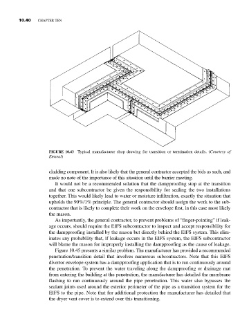
FIGURE 10.43 Typical manufacturer shop drawing for transition or termination details. (Courtesy of
Emseal)
cladding component. It is also likely that the general contractor accepted the bids as such, and
made no note of the importance of this situation until the barrier meeting.
It would not be a recommended solution that the dampproofing stop at the transition
and that one subcontractor be given the responsibility for sealing the two installations
together. This would likely lead to water or moisture infiltration, exactly the situation that
upholds the 90%/1% principle. The general contractor should assign the work to the sub-
contractor that is likely to complete their work on the envelope first, in this case most likely
the mason.
As importantly, the general contractor, to prevent problems of “finger-pointing” if leak-
age occurs, should require the EIFS subcontractor to inspect and accept responsibility for
the dampproofing installed by the mason but directly behind the EIFS system. This elim-
inates any probability that, if leakage occurs in the EIFS system, the EIFS subcontractor
will blame the mason for improperly installing the dampproofing as the cause of leakage.
Figure 10.45 presents a similar problem. The manufacturer has provided a recommended
penetration/transition detail that involves numerous subcontractors. Note that this EIFS
divertor envelope system has a dampproofing application that is to run continuously around
the penetration. To prevent the water traveling along the dampproofing or drainage mat
from entering the building at the penetration, the manufacturer has detailed the membrane
flashing to run continuously around the pipe penetration. This water also bypasses the
sealant joints used around the exterior perimeter of the pipe as a transition system for the
EIFS to the pipe. Note that for additional protection the manufacturer has detailed that
the dryer vent cover is to extend over this transitioning.