
Page 492 - Corrosion Engineering Principles and Practice
P. 492
458 C h a p t e r 1 1 M a t e r i a l s S e l e c t i o n , Te s t i n g , a n d D e s i g n C o n s i d e r a t i o n s 459
drawn under tanks by surface tension effects. Six common tank bot-
tom arrangements are illustrated here with comments from a corro-
sion engineering point of view.
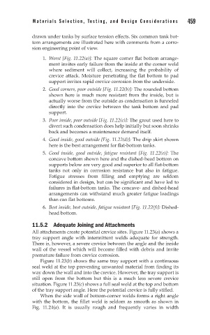
1. Worst [Fig. 11.22(a)]: The square corner flat bottom arrange-
ment invites early failure from the inside at the corner weld
where sediment will collect, increasing the probability of
crevice attack. Moisture penetrating the flat bottom to pad
support invites rapid crevice corrosion from the underside.
2. Good corners, poor outside [Fig. 11.22(b)]: The rounded bottom
shown here is much more resistant from the inside, but is
actually worse from the outside as condensation is funneled
directly into the crevice between the tank bottom and pad
support.
3. Poor inside, poor outside [Fig. 11.22(c)]: The grout used here to
divert such condensation does help initially but soon shrinks
back and becomes a maintenance demand itself.
4. Good inside, good outside [Fig. 11.22(d)]: The drip skirt shown
here is the best arrangement for flat-bottom tanks.
5. Good inside, good outside, fatigue resistant [Fig. 11.22(e)]: The
concave bottom shown here and the dished-head bottom on
supports below are very good and superior to all flat-bottom
tanks not only in corrosion resistance but also in fatigue.
Fatigue stresses from filling and emptying are seldom
considered in design, but can be significant and have led to
failures in flat-bottom tanks. The concave- and dished-head
arrangements can withstand much greater fatigue loadings
than can flat bottoms.
6. Best inside, best outside, fatigue resistant [Fig. 11.22(f)]: Dished-
head bottom.
11.5.2 Adequate Joining and Attachments
All attachments create potential crevice sites. Figure 11.23(a) shows a
tray support angle with intermittent welds adequate for strength.
There is, however, a severe crevice between the angle and the inside
wall of the vessel which will become filled with debris and invite
premature failure from crevice corrosion.
Figure 11.23(b) shows the same tray support with a continuous
seal weld at the top preventing unwanted material from finding its
way down the wall and into the crevice. However, the tray support is
still open from the bottom but this is a much less severe crevice
situation. Figure 11.23(c) shows a full seal weld at the top and bottom
of the tray support angle. Here the potential crevice is fully stifled.
When the side wall of bottom-corner welds forms a right angle
with the bottom, the fillet weld is seldom as smooth as shown in
Fig. 11.24(a). It is usually rough and frequently varies in width