
Page 630 - Corrosion Engineering Principles and Practice
P. 630
592 C h a p t e r 1 4 P r o t e c t i v e C o a t i n g s 593
for example, the initiation or further oxidation of the iron can occur.
A corrosion cell comparable to that in a pit on freely exposed iron
may then develop. If ionic contaminants are present at the interface
between the coating and the steel, the electrolyte would be more
conductive and thus favor a more vigorous cell action.
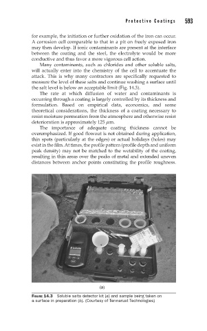
Many contaminants, such as chlorides and other soluble salts,
will actually enter into the chemistry of the cell to accentuate the
attack. This is why many contractors are specifically requested to
measure the level of these salts and continue washing a surface until
the salt level is below an acceptable limit (Fig. 14.3).
The rate at which diffusion of water and contaminants is
occurring through a coating is largely controlled by its thickness and
formulation. Based on empirical data, economics, and some
theoretical considerations, the thickness of a coating necessary to
resist moisture permeation from the atmosphere and otherwise resist
deterioration is approximately 125 m m.
The importance of adequate coating thickness cannot be
overemphasized. If good flowout is not obtained during application,
thin spots (particularly at the edges) or actual holidays (holes) may
exist in the film. At times, the profile pattern (profile depth and uniform
peak density) may not be matched to the wetability of the coating,
resulting in thin areas over the peaks of metal and extended uneven
distances between anchor points constituting the profile roughness.
(a)
FIGURE 14.3 Soluble salts detector kit (a) and sample being taken on
a surface in preparation (b). (Courtesy of Termarust Technologies)