
Page 713 - Corrosion Engineering Principles and Practice
P. 713
666 C h a p t e r 1 5 H i g h - Te m p e r a t u r e C o r r o s i o n 667
H /H O ratio 10 –8 10 –6 10 –4 pO 2
2
2
CO/CO ratio 10 –8 10 –6 10 –4 10 –2
2
10 –2
O 0
1
–100 M 10 –2
2CO + O 2 = 2CO 2
M M 2Co + O 2 = 2CoO 1
4Cu + O 2 = 2Cu 2 O 2Fe + O 2 = 2FeO 10 –4
2Ni + O 2 = 2NiO
–200
M
–300 2
M 10
M 10 –6
C + O 2 = CO 2 10 2
∆G 0 = RT ln O 2 (kJ/mole O 2 ) –600 M Si + O 2 = SiO 2 M B 10 4 10 –12
–400
H –500 2Zn + O 2 = 2ZnO B 3 M 10 4 10 –8
C 4 Cr + O 2 = 2 / Cr 2 O 3 2C + O 2 = 2CO –10
/
3
–700
–800 10 6 10 –14
10
4 Al + O 2 = 2 / Al 2 O 2 10 6
3
–900 / B –16
3
M 2Ca + O 2 = 2CaO B 10 8 10
–1000
2Mg + O 2 = 2MgO M M Change of state element oxide 8 10 –18
–1100 Melting point M B M 10
Boiling point
B
10 10 10 –20
–1200
0 200 400 600 800 1000 1200 1400 1600 1800 2000 2200 2400
Temperature(°C) –22
H /H O ratio 10 14 10 12 10 10 10
2
2
0 K CO/CO ratio 10 12
2
10 –50 10 –30 10 –24
pO
2
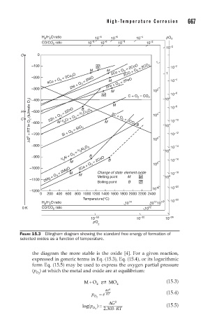
FIGURE 15.3 Ellingham diagram showing the standard free energy of formation of
selected oxides as a function of temperature.
the diagram the more stable is the oxide [4]. For a given reaction,
expressed in generic terms in Eq. (15.3), Eq. (15.4), or its logarithmic
form Eq. (15.5) may be used to express the oxygen partial pressure
(p ) at which the metal and oxide are at equilibrium:
O 2
M O MO (15.3)
+
2
2
G
∆
0
p = e RT (15.4)
O 2
log(p ) = ∆ G 0 (15.5)
O 2 . 2 303⋅ RT