
Page 236 - DSP Integrated Circuits
P. 236
Problems 221
[32] Smith L.M., Bomar B.W., Joseph R.D., and Yang G.C.: Floating-Point
Roundoff Noise Analysis of Second-Order State-Space Digital Filter
Structures, IEEE Trans, on Circuits and Systems, Vol. CAS-39, No. 2, pp. 90-
98, Feb. 1992.
[33] Taylor F.J.: Digital Filter Design Handbook, Marcel Dekker, New York, 1983.
[34] Tran-Thong and Liu B.: Fixed-Point FFT Error Analysis, IEEE Trans, on
Acoustics, Speech, and Signal Processing, Vol. ASSP-24, No. 6, pp. 563-573,
1976.
[35] Zeng B. and Neuvo Y: Analysis of Floating Point Roundoff Errors Using
Dummy Multiplier Coefficient Sensitivities, IEEE Trans, on Circuits and
Systems, Vol. CAS-38, No. 6, pp. 590-601, June 1991.
PROBLEMS
5.1 A two's-complement number is multiplied by a factor 0.5 and then quantized
to the original word length. Determine both the average value and the
variance of the quantization error.
5.2 Show that the quantization scheme, discussed in section 5.4, will suppress
parasitic oscillations.
5.3 Show that the simplified scheme, discussed in section 5.4, will suppress zero-
input parasitic oscillations for second-order allpass sections with poles on the
imaginary axis in the z-plane.
5.4 Show that a two-port adaptor is pseudo-lossless.
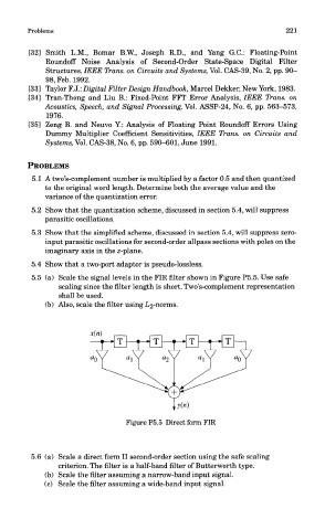
5.5 (a) Scale the signal levels in the FIR filter shown in Figure P5.5. Use safe
scaling since the filter length is short. Two's-complement representation
shall be used.
(b) Also, scale the filter using L2-norms.
Figure P5.5 Direct form FIR
5.6 (a) Scale a direct form II second-order section using the safe scaling
criterion. The filter is a half-band filter of Butterworth type.
(b) Scale the filter assuming a narrow-band input signal.
(c) Scale the filter assuming a wide-band input signal.