
Page 253 - DSP Integrated Circuits
P. 253
238 Chapter 6 DSP Algorithms
Finally, we obtain the signal-flow graph
in precedence form by connecting the nodes in
Figure 6.24 with the delay branches and the
arithmetic branches according to the original Figure 6.23 The last addition
has been removed
signal-flow graph. Notice the two registers
that are needed for the delay elements.
Figure 6.24 Precedence of node sets
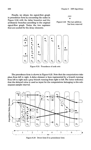
The precedence form is shown in Figure 6.25. Note that the computations take
place from left to right. A delay element is here represented by a branch running
from left to right and a gray branch running from right to left. The latter indicates
that the delayed value is used as input for the computations belonging to the sub-
sequent sample interval.
Figure 6.25 Direct form II in precedence form