
Page 251 - DSP Integrated Circuits
P. 251
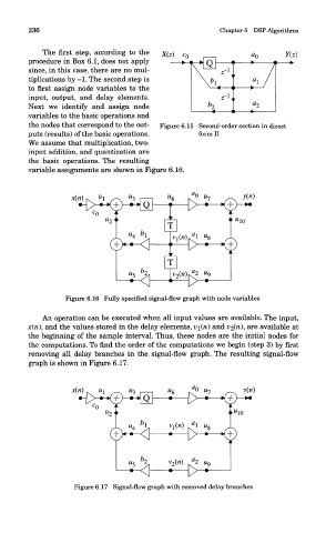
236                                                Chapters DSP Algorithms

            The first step, according to the
        procedure in Box 6.1, does not apply
        since, in this case, there are no mul-
        tiplications by -1. The second step is
        to first assign node variables to the
        input, output, and delay elements.
        Next we identify and assign node
        variables to the basic operations and
        the nodes that correspond to the out-  Figure 6.15 Second-order section in direct
        puts (results) of the basic operations.       form II
        We assume that multiplication, two-
        input addition, and quantization are
        the basic operations. The resulting
        variable assignments are shown in Figure 6.16.


                  Figure 6.16 Fully specified signal-flow graph with node variables

            An operation can be executed when all input values are available. The input,
        x(n), and the values stored in the delay elements, v\(ri) and v<z(ri), are available at
        the beginning of the sample interval. Thus, these nodes are the initial nodes for
        the computations. To find the order of the computations we begin (step 3) by first
        removing all delay branches in the signal-flow graph. The resulting signal-flow
        graph is shown in Figure 6.17.


                    Figure 6.17 Signal-flow graph with removed delay branches