
Page 247 - DSP Integrated Circuits
P. 247
232 Chapter 6 DSP Algorithms
In redundant arithmetic, which processes the MSB first, the carry will propa-
gate for a few bits only. The latency is determined by the length (number of bits) of
the carry propagation. We will later show that throughput in a recursive algo-
rithm will be determined by the total latency of the operations in the recursive
loops and not by the throughput of the basic operations (multiplications and addi-
tions) within the loop.
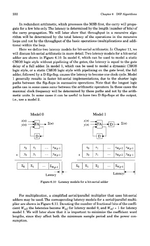
Here we define two latency models for bit-serial arithmetic. In Chapter 11, we
will discuss bit-serial arithmetic in more detail. Two latency models for a bit-serial
adder are shown in Figure 6.10. In model 0, which can be used to model a static
CMOS logic style without pipelining of the gates, the latency is equal to the gate
delay of a full adder. In model 1, which can be used to model a dynamic CMOS
logic style, or a static CMOS logic style with pipelining on the gate level, the full
adder, followed by a D flip-flop, causes the latency to become one clock cycle. Model
1 generally results in faster bit-serial implementations, due to the shorter logic
paths between the flip-flops in successive operations. Note that the longest logic
paths can in some cases occur between the arithmetic operators. In these cases the
maximal clock frequency will be determined by these paths and not by the arith-
metic units. In some cases it can be useful to have two D flip-flops at the output,
i.e., use a model 2.
Figure 6.10 Latency models for a bit-serial adder
For multiplication, a simplified serial/parallel multiplier that uses bit-serial
adders may be used. The corresponding latency models for a serial/parallel multi-
plier are shown in Figure 6.11. Denoting the number of fractional bits of the coeffi-
cient W af, the latencies become W af for latency model 0, and W af + I for latency
model 1. We will later show that it is important to minimize the coefficient word
lengths, since they affect both the minimum sample period and the power con-
sumption.