
Page 100 - Decision Making Applications in Modern Power Systems
P. 100
Uncertainty analysis and risk assessment Chapter | 3 67
PDC
PMU
Optical
fiber
ON Transceiver Repeater Transceiver
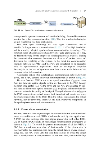
FIGURE 3.4 Optical fiber synchrophasor communication system.
propagation in open environment and multipath fading, the satellite commu-
nication has a large propagation delay [10]. Thus the wireless technologies
are not reliable for real-time applications.
The fiber optic technology has low signal attenuation and is
suitable for long-distance communication [11,12]. It offers high bandwidth
and is a widely adopted synchrophasor communication technology. The
communication channel can be shared by other data applications or it may
be dedicated solely for the purpose of synchrophasor data transfer. Sharing
the communication resources increases the chances of packet losses and
decreases the reliability of the system. In this work the communication
channels between the PMUs and the PDC are considered to be dedicated
only for synchrophasor applications. Such an assumption simplifies
the analysis as the loss of synchrophasor data is due to the failure of the
communication infrastructure.
A dedicated optical fiber synchrophasor communication network between
a PMU and a PDC consists of several components that are shown in Fig. 3.4.
The data from the PMU is sent to an optical transceiver (C PMU ) to trans-
form the data into optical signals, which are then sent to the PDC through
the fiber optic cables (C 2 ). As the PMU and the PDC are separated by sev-
eral hundred kilometers, optical repeaters (C 3 ) are placed at intermediate dis-
tances to maintain the quality of the signal. The optical transceiver (C PDC )at
the PDC converts these optical signals back into electrical signals and sends
the synchrophasor data to the PDC. Thus the optical transceivers, the optical
repeaters, and the fiber optic cables are the main constituent components of
the synchrophasor communication networks.
3.1.3 Phasor data concentrator
The PDC creates a time-aligned output data stream from the phasor measure-
ments received from several PMUs, which can be used by other applications.
A PDC can also exchange this time-aligned phasor data with other PDCs.
Use of multiple PDCs results in hierarchical communication architecture, as
shown in Fig. 3.1. To record the phasor measurements of all the PMUs, a
PDC has a maximum wait time of 1 4 seconds. If the phasor data is
received within this maximum wait time, the output data is created immedi-
ately; else, the PDC waits until the time limit expires to create the output
data. A quality check is then performed on the PMU data, and suitable flags