
Page 103 - Decision Making Applications in Modern Power Systems
P. 103
70 Decision Making Applications in Modern Power Systems
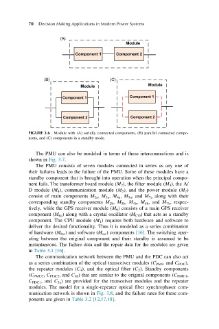
(A)
Module
Component 1 Component 2
(B) (C)
Module Module
Component 1 Component 1
Component 2 Component 2
FIGURE 3.6 Module with (A) serially connected components, (B) parallel connected compo-
nents, and (C) components in a standby mode.
The PMU can also be modeled in terms of these interconnections and is
shown in Fig. 3.7.
The PMU consists of seven modules connected in series as any one of
their failures leads to the failure of the PMU. Some of these modules have a
standby component that is brought into operation when the principal compo-
nent fails. The transformer board module (M 2 ), the filter module (M 3 ), the A/
D module (M 4 ), communication module (M 5 ), and the power module (M 7 )
consist of main components M 2a , M 3a , M 4a , M 5a , and M 7a along with their
corresponding standby components M 2b , M 3b , M 4b , M 5b , and M 7b , respec-
tively, while the GPS receiver module (M 6 ) consists of a main GPS receiver
component (M 6a ) along with a crystal oscillator (M CO ) that acts as a standby
component. The CPU module (M 1 ) requires both hardware and software to
deliver the desired functionality. Thus it is modeled as a series combination
of hardware (M hw ) and software (M sw ) components [16]. The switching oper-
ating between the original component and their standby is assumed to be
instantaneous. The failure data and the repair data for the modules are given
in Table 3.1 [16].
The communication network between the PMU and the PDC can also act
as a series combination of the optical transceiver modules (C PMU and C PDC ),
the repeater modules (C 3 ), and the optical fiber (C 2 ). Standby components
(C PMU2 , C PDC2 , and C 3b ) that are similar to the original components (C PMU1 ,
C PDC1 , and C 3a ) are provided for the transceiver modules and the repeater
modules. The model for a single-repeater optical fiber synchrophasor com-
munication network is shown in Fig. 3.8, and the failure rates for these com-
ponents are given in Table 3.2 [12,17,18].