
Page 98 - Decision Making Applications in Modern Power Systems
P. 98
Uncertainty analysis and risk assessment Chapter | 3 65
GPS
GPS satellite
receiver
module
Data collection module
CT/PT Antialiasing A/D Communication
module filter converter CPU module
To the
communication
network
Power
supply
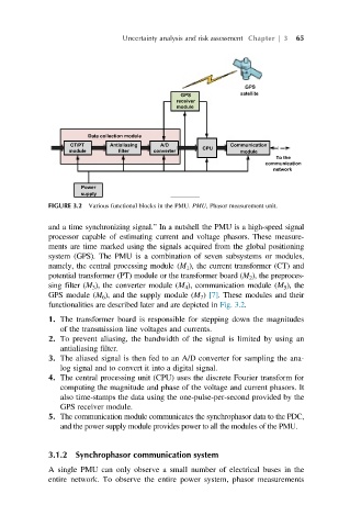
FIGURE 3.2 Various functional blocks in the PMU. PMU, Phasor measurement unit.
and a time synchronizing signal.” In a nutshell the PMU is a high-speed signal
processor capable of estimating current and voltage phasors. These measure-
ments are time marked using the signals acquired from the global positioning
system (GPS). The PMU is a combination of seven subsystems or modules,
namely, the central processing module (M 1 ), the current transformer (CT) and
potential transformer (PT) module or the transformer board (M 2 ), the preproces-
sing filter (M 3 ), the converter module (M 4 ), communication module (M 5 ), the
GPS module (M 6 ), and the supply module (M 7 ) [7]. These modules and their
functionalities are described later and are depicted in Fig. 3.2.
1. The transformer board is responsible for stepping down the magnitudes
of the transmission line voltages and currents.
2. To prevent aliasing, the bandwidth of the signal is limited by using an
antialiasing filter.
3. The aliased signal is then fed to an A/D converter for sampling the ana-
log signal and to convert it into a digital signal.
4. The central processing unit (CPU) uses the discrete Fourier transform for
computing the magnitude and phase of the voltage and current phasors. It
also time-stamps the data using the one-pulse-per-second provided by the
GPS receiver module.
5. The communication module communicates the synchrophasor data to the PDC,
and the power supply module provides power to all the modules of the PMU.
3.1.2 Synchrophasor communication system
A single PMU can only observe a small number of electrical buses in the
entire network. To observe the entire power system, phasor measurements