
Page 108 - Decision Making Applications in Modern Power Systems
P. 108
74 Decision Making Applications in Modern Power Systems
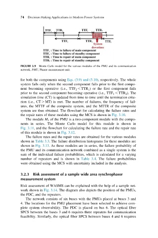
FIGURE 3.9 Monte Carlo model for the various modules of the PMU and its communication
network. PMU, Phasor measurement unit.
for both the components using Eqs. (3.9) and (3.10), respectively. The whole
system fails only when the second component fails prior to the first compo-
nent becoming operative (i.e., TTF 2 , TTR 1 ) or the first component fails
prior to the second component becoming operative (i.e., TTF 1 , TTR 2 ). The
simulation time (CT) is updated from time to time until the termination crite-
rion (i.e., CT . MT) is met. The number of failures, the frequency of fail-
ures, the MTTF of the composite system, and the MTTR of the composite
system are thus obtained. The flowchart for calculating the failure rates and
the repair rates of these modules using the MCS is shown in Fig. 3.10.
The module M 1 of the PMU is a two-component module with the compo-
nents in series. The Monte Carlo model for this module is shown in
Fig. 3.11, and the flowchart for calculating the failure rate and the repair rate
of this module is shown in Fig. 3.12.
The failure rates and the repair rates are obtained for the various modules
shown in Table 3.3. The failure distribution histograms for these modules are
shown in Fig. 3.13. As these modules are in series, the failure probability of
the PMU and its communication network combined as a single system is the
sum of the individual failure probabilities, which is calculated for a varying
number of repeaters and is shown in Table 3.4. The failure probabilities
were obtained using the MCS with uncertainty included in the analysis.
3.2.3 Risk assessment of a sample wide area synchrophasor
measurement system
Risk assessment of WASMS can be explained with the help of a sample net-
work shown in Fig. 3.14. The diagram also depicts the position of the PMUs,
the PDC, and the repeaters.
The network consists of six buses with the PMUs placed at buses 3 and
4. The locations for the PMU placement have been selected to achieve com-
plete system observability. The PDC is placed on bus 6. The optical fiber
SPCS between the buses 3 and 6 requires three repeaters for communication
feasibility. Similarly, the optical fiber SPCS between buses 4 and 6 requires