
Page 111 - Decision Making Applications in Modern Power Systems
P. 111
Uncertainty analysis and risk assessment Chapter | 3 77
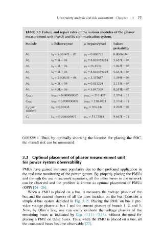
TABLE 3.3 Failure and repair rates of the various modules of the phasor
measurement unit (PMU) and its communication system.
Module λ (failures/year) μ (repairs/year) Failure
probability
λ 1 5 5.00347E 2 07 μ 1 5 0.000721 0.0006934
M 1
M 2 λ 2 5 5E 2 06 μ 2 5 8.838459224 5.657E 2 07
λ 3 5 5E 2 06 μ 3 5 26.8536 1.862E 2 07
M 3
M 4 λ 4 5 5E 2 06 μ 4 5 8.838459224 5.657E 2 07
λ 5 5 5.00001E 2 06 μ 5 5 3.335687 1.499E 2 06
M 5
M 6 λ 6 5 5E 2 09 μ 6 5 0.023224 2.153E 2 07
M 7 λ 7 5 5E 2 06 μ 7 5 5.847309 8.551E 2 07
C PMU λ PMU 5 0.000000005 μ PMU 5 210.4021 2.376E 2 11
C PDC λ PDC 5 0.000000005 μ PDC 5 210.4021 2.376E 2 11
C 2 (per λ 2c 5 0.00438 μ 2c 5 104.244 4.202E 2 05
100 km)
C 3 λ 3c 5 0.000000005 μ 3c 5 51.72361 9.667E 2 11
0.0032914. Thus, by optimally choosing the location for placing the PDC,
the overall risk can be minimized.
3.3 Optimal placement of phasor measurement unit
for power system observability
PMUs have gained immense popularity due to their profound application in
the real-time monitoring of the power system. By properly placing the PMUs
and through the use of network equations, all the other buses in the network
can be observed and the problem is known as optimal placement of PMUs
(OPP) [24 26].
When a PMU is placed on a bus, it measures the voltage phasor of the
bus and the current phasors of all the lines incident on the bus. Consider a
simple 4-bus system depicted in Fig. 3.15. Placing the PMU on bus 1 pro-
vides voltage phasor at bus 1 and the current phasors of branch 1, 2, and 3.
Now, by Ohm’s law, one can easily evaluate the voltage phasors of the
remaining buses as indicated by Eqs. (3.11) (3.13), without the need for
placing a PMU on these buses. Thus, when the PMU is placed on a bus, all
the connected buses become observable [27].