
Page 137 - Decision Making Applications in Modern Power Systems
P. 137
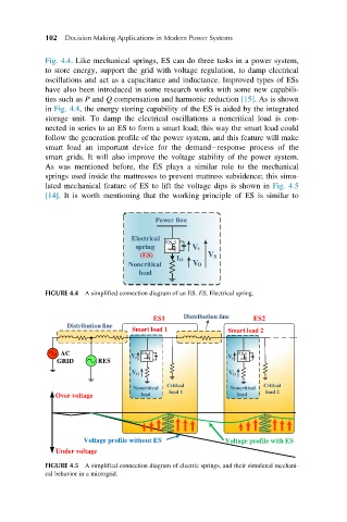
102  Decision Making Applications in Modern Power Systems


            Fig. 4.4. Like mechanical springs, ES can do three tasks in a power system,
            to store energy, support the grid with voltage regulation, to damp electrical
            oscillations and act as a capacitance and inductance. Improved types of ESs
            have also been introduced in some research works with some new capabili-
            ties such as P and Q compensation and harmonic reduction [15]. As is shown
            in Fig. 4.4, the energy storing capability of the ES is aided by the integrated
            storage unit. To damp the electrical oscillations a noncritical load is con-
            nected in series to an ES to form a smart load; this way the smart load could
            follow the generation profile of the power system, and this feature will make
            smart load an important device for the demand response process of the
            smart grids. It will also improve the voltage stability of the power system.
            As was mentioned before, the ES plays a similar role to the mechanical
            springs used inside the mattresses to prevent mattress subsidence; this simu-
            lated mechanical feature of ES to lift the voltage dips is shown in Fig. 4.5
            [14]. It is worth mentioning that the working principle of ES is similar to


                                        Power line

                                  Electrical
                                          ES
                                   spring         e V
                                    (ES)             V S
                                             I O
                                 Noncritical     V O
                                    load
            FIGURE 4.4 A simplified connection diagram of an ES. ES, Electrical spring.


                                       ES1     Distribution line  ES2
                  Distribution line
                                  Smart load 1            Smart load 2

                AC                  ES                      ES
                                  V e                     V e
               GRID      RES
                                  V O                     V O
                                          Critical                Critical
                                  Noncritical             Noncritical
               Over voltage         load   load 1           load   load 2


                      Voltage profile without ES         Voltage profile with ES
               Under voltage
            FIGURE 4.5 A simplified connection diagram of electric springs, and their simulated mechani-
            cal behavior in a microgrid.