
Page 136 - Decision Making Applications in Modern Power Systems
P. 136
Power quality issues of smart microgrids Chapter | 4 101
V Sa
I Sa I La
V Sb
I SIa
I Sb I Lb
V Sc I SIb
Z S I Sc I Lc
I SIc
V DCa V DCb V DCc
V AFa V AFb V AFc
V PWMA V PWMB V PWMC
V Ca V Cb V Cc
Fundamental component
extraction Resonant converter
I Sh
K P I Sl1 I Slh
V DC_PWM I Sl
V afh
Σ K rh *S
S + (hω ) 2
2
o
PI V DCa
V DCb
φ ref = 0
I S1 V S1 DC voltage control V DC * V DCc
Phase φ
V S1
V Sa detection PI * V af1
DPF control
V Sb
V Sc Phase A control block
Phase B control block
Phase C control block
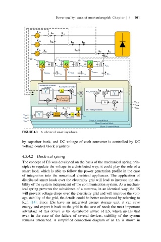
FIGURE 4.3 A scheme of smart impedance.
by capacitor bank, and DC voltage of each converter is controlled by DC
voltage control block regulates.
4.3.4.2 Electrical spring
The concept of ES was developed on the basis of the mechanical spring prin-
ciples to regulate the voltage in a distributed way; it could play the role of a
smart load, which is able to follow the power generation profile in the case
of integration into the noncritical electrical appliances. The application of
distributed smart loads over the electricity grid will lead to increase the sta-
bility of the system independent of the communication system. As a mechan-
ical spring prevents the subsidence of a mattress, in an identical way, the ES
will prevent voltage drops over the electricity grid and will improve the volt-
age stability of the grid, the details could be better understood by referring to
Ref. [14]. Since ESs have an integrated energy storage unit, it can save
energy and export it back to the grid in the case of need; the most important
advantage of this device is the distributed nature of ES, which means that
even in the case of the failure of several devices, stability of the system
remains untouched. A simplified connection diagram of an ES is shown in