
Page 321 - Decision Making Applications in Modern Power Systems
P. 321
282 Decision Making Applications in Modern Power Systems
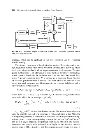
FIGURE 11.1 Schematic diagram of LFC/AGC system. AGC, Automatic generation control;
LFC, load-frequency control.
strategy, which can be deployed in real-time operation, can be computed
simultaneously.
This strategy makes use of the distribution vectors. Depending on the out-
age magnitude and the wind power deviation, the amount of power by which
each generating unit should adjust its production can be determined. The pro-
posed methodology is an alternative to other methods for reserve scheduling,
which account implicitly for real-time response via their day-ahead deci-
i
sions. A power correction term R is defined as a piecewise linear function
of the total generation-load mismatch. This term shows the amount of the
power that each generator should compensate for given an imbalance and is
directly related to the reserves.
i
i
i
R P w Þ 5 d i max 2P P w Þ 2 d i max P P w Þ ; iAϒ ð11:1Þ
ð
ð
ð
up m down m
1 1
where max 1 ( ) 5 max( ; 0). Variable P m Aℜ denotes the generation-load
mismatch, which for each outage is given by
X f i i i
i
P P w Þ 5 P w;k 2 P 2 c P L 1 c P G 1 c P w ; for all iAϒ
ð
m w;k L G w
kAZ w =K i
ð11:2Þ
d up ; d down Aℜ NG are the distribution vectors. The sum of these elements
must be equal to one and, if a generator is not contributing to the AGC, the
corresponding element in the vector will be zero. To distinguish between up-
spinning reserves and down-spinning reserves, the indices “up” and “down”
are used. If P m is negative, up-spinning reserves are provided, and the pro-
duction of the generators is increased accordingly. In the opposite case the
second term of (11.1) is active, and down-spinning reserves are provided. It