
Page 409 - Decision Making Applications in Modern Power Systems
P. 409
370 Decision Making Applications in Modern Power Systems
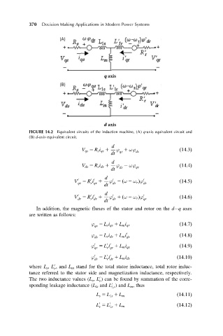
FIGURE 14.2 Equivalent circuits of the induction machine, (A) q-axis equivalent circuit and
(B) d-axis equivalent circuit.
d
V qs 5 R s i qs 1 ϕ 1 ωϕ ds ð14:3Þ
qs
dt
d
V ds 5 R s i ds 1 ϕ 2 ωϕ qs ð14:4Þ
ds
dt
d
0 0
0
0
V 5 R i 1 ϕ 2 ω 2 ω r Þϕ 0 ð14:5Þ
ð
r qr
qr
dt dr dr
d
V 5 R i 1 ϕ 1 ω 2 ω r Þϕ 0 ð14:6Þ
0
0 0
0
ð
dr r dr dr qr
dt
In addition, the magnetic fluxes of the stator and rotor on the d q axes
are written as follows:
ϕ 5 L s i qs 1 L m i qr ð14:7Þ
qs
ϕ 5 L s i ds 1 L m i 0 dr ð14:8Þ
ds
0 0 0
ϕ 5 L i 1 L m i qs ð14:9Þ
qr r qr
0 0 0
ϕ 5 L i 1 L m i ds ð14:10Þ
dr r dr
0
where L s , L , and L m stand for the total stator inductance, total rotor induc-
r
tance referred to the stator side and magnetization inductance, respectively.
The two inductance values (L s , L ) can be found by summation of the corre-
0
r
sponding leakage inductance (L ls and L ) and L m , thus
0
1r
L s 5 L 1s 1 L m ð14:11Þ
0 0
L 5 L 1 L m ð14:12Þ
r 1r