
Page 412 - Decision Making Applications in Modern Power Systems
P. 412
Integration of fixed-speed wind Chapter | 14 373
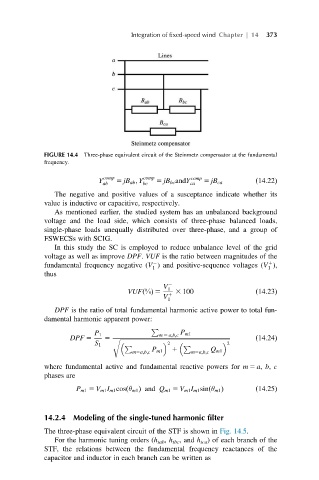
FIGURE 14.4 Three-phase equivalent circuit of the Steinmetz compensator at the fundamental
frequency.
comp comp comp
Y 5 jB ab ; Y 5 jB bc andY ð14:22Þ
ab bc ca 5 jB ca
The negative and positive values of a susceptance indicate whether its
value is inductive or capacitive, respectively.
As mentioned earlier, the studied system has an unbalanced background
voltage and the load side, which consists of three-phase balanced loads,
single-phase loads unequally distributed over three-phase, and a group of
FSWECSs with SCIG.
In this study the SC is employed to reduce unbalance level of the grid
voltage as well as improve DPF. VUF is the ratio between magnitudes of the
2
1
fundamental frequency negative (V ) and positive-sequence voltages (V ),
1 1
thus
V 2
VUF %ðÞ 5 1 3 100 ð14:23Þ
V 1
1
DPF is the ratio of total fundamental harmonic active power to total fun-
damental harmonic apparent power:
P
P 1 m 5 a;b;c P m1
DPF 5 5 r ffiffiffiffiffiffiffiffiffiffiffiffiffiffiffiffiffiffiffiffiffiffiffiffiffiffiffiffiffiffiffiffiffiffiffiffiffiffiffiffiffiffiffiffiffiffiffiffiffiffiffiffiffiffiffiffiffiffiffiffiffiffiffiffiffiffiffiffiffiffiffiffi ð14:24Þ
S 1 2 2
P 1 P
m5a;b;c P m1 m5a;b;c Q m1
where fundamental active and fundamental reactive powers for m 5 a, b, c
phases are
ð
ð
P m1 5 V m1 I m1 cos θ m1 Þ and Q m1 5 V m1 I m1 sin θ m1 Þ ð14:25Þ
14.2.4 Modeling of the single-tuned harmonic filter
The three-phase equivalent circuit of the STF is shown in Fig. 14.5.
For the harmonic tuning orders (h tab , h tbc , and h tca ) of each branch of the
STF, the relations between the fundamental frequency reactances of the
capacitor and inductor in each branch can be written as