
Page 416 - Decision Making Applications in Modern Power Systems
P. 416
Integration of fixed-speed wind Chapter | 14 377
14.4 Simulation results and discussion
For the simulations the test system, given in Fig. 14.1, has three-phase unbal-
anced and nonsinusoidal utility voltages with the fundamental harmonic pha-
sor components, unbalance level, and total harmonic distortion measured as
3
3
3
V Sa 5 2:31+0 kV, V Sb 5 2:31+ 2 120 kV, V Sc 5 2:42+120 kV,
VUF S 5 1.65%, and THDV S 5 3.8%, respectively.
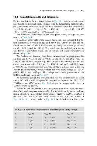
The harmonic components of the three-phase utility voltages are pre-
sented in Table 14.1.
In addition, utility side of the system has a star star connected distribu-
tion transformer, of which ratings are 5 MVA and 4.16/0.4 kV, and the bal-
anced supply line, of which fundamental frequency impedance parameters
are R S 5 0.01 Ω and X S 5 0.1 Ω. The transformer is modeled by using its
well-known T-equivalent circuit, and its ratings and circuit parameters are
shown in Fig. 14.6.
The fundamental frequency impedance parameters of the single-phase lin-
ear load are R L 5 0.11 Ω and X L 5 0.67 Ω, and its P 1 and DPF values as
480 kW and 98.64%, respectively. The six-pulse uncontrolled rectifier has
circuit parameters as R 5 0.4 Ω and C 5 1000 μF, and its P 1 and DPF values
as 650 kW and 99.70%, respectively. The SCIGs, which are used in the five
FSWECSs, have power, voltage, current and rotor speed ratings as 110 kW,
400 V, 182 A and 1487 rpm. The ratings and circuit parameters of the
SCIG’s model are shown in Fig. 14.7.
As mentioned earlier, the consumer side has two compensators as a STF
and a SC, which will be optimally designed to improve the PPL, VUF,
THDV Mean , and DPF values. Fig. 14.8 shows the system under study in
Matlab/Simulink platform.
For the PLs of the FSWECs into the system from 0% to 60%, the varia-
tion of the total rms phase currents (I Ga , I Gb , I Gc ) injected by them, total har-
monic distortion values of the phase voltages (THDV a , THDV b , THDV c )at
the PCC, and the VUF and DPF values at the PCC are plotted in
Figs. 14.9 14.11, respectively. In Fig. 14.9 the dashed vertical line points
TABLE 14.1 Harmonic components of the three-phase utility voltage.
h V Sah (V) V Sbh (V) V Sch (V)
5 70+0 3 70+ 2 5U120 3 73+5U120 3
7 46+0 3 46+ 2 7U120 3 49+7U120 3
11 23+0 3 23+ 2 11U120 3 24+11U120 3
13 23+0 3 23+ 2 13U120 3 24+13U120 3