
Page 421 - Decision Making Applications in Modern Power Systems
P. 421
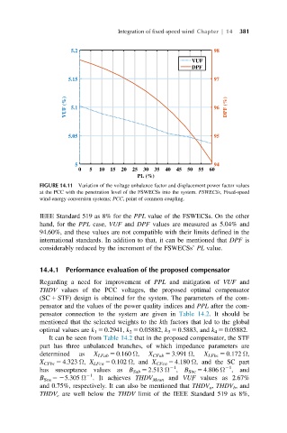
Integration of fixed-speed wind Chapter | 14  381


                      5.2                                        98
                                                           VUF
                                                           DPF
                      5.15                                       97


                     VUF (%)  5.1                                96  DPF (%)


                      5.05                                       95


                        5                                        94
                         0  5  10  15  20  25  30  35  40  45  50  55  60
                                          PL (%)
             FIGURE 14.11 Variation of the voltage unbalance factor and displacement power factor values
             at the PCC with the penetration level of the FSWECSs into the system. FSWECSs, Fixed-speed
             wind energy conversion systems; PCC, point of common coupling.

             IEEE Standard 519 as 8% for the PPL value of the FSWECSs. On the other
             hand, for the PPL case, VUF and DPF values are measured as 5.04% and
             94.60%, and these values are not compatible with their limits defined in the
             international standards. In addition to that, it can be mentioned that DPF is
             considerably reduced by the increment of the FSWECSs’ PL value.


             14.4.1 Performance evaluation of the proposed compensator
             Regarding a need for improvement of PPL and mitigation of VUF and
             THDV values of the PCC voltages, the proposed optimal compensator
             (SC 1 STF) design is obtained for the system. The parameters of the com-
             pensator and the values of the power quality indices and PPL after the com-
             pensator connection to the system are given in Table 14.2. It should be
             mentioned that the selected weights to the kth factors that led to the global
             optimal values are k 1 5 0.2941, k 2 5 0.05882, k 3 5 0.5883, and k 4 5 0.05882.
                It can be seen from Table 14.2 that in the proposed compensator, the STF
             part has three unbalanced branches, of which impedance parameters are
             determined  as  X LFab 5 0.160 Ω,  X CFab 5 3.991 Ω,  X LFbc 5 0.172 Ω,
             X CFbc 5 4.323 Ω, X LFca 5 0.102 Ω, and X CFca 5 4.180 Ω, and the SC part
                                                    21
                                                                     21
             has susceptance values as B Sab 5 2.513 Ω , B Sbc 5 4.806 Ω , and
                           21
             B Sca 525.305 Ω . It achieves THDV Mean and VUF values as 2.67%
             and 0.75%, respectively. It can also be mentioned that THDV a , THDV b , and
             THDV c are well below the THDV limit of the IEEE Standard 519 as 8%,