
Page 422 - Decision Making Applications in Modern Power Systems
P. 422
382 Decision Making Applications in Modern Power Systems
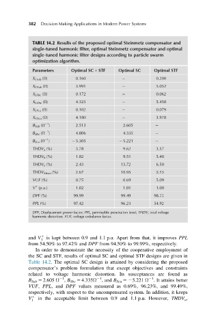
TABLE 14.2 Results of the proposed optimal Steinmetz compensator and
single-tuned harmonic filter, optimal Steinmetz compensator and optimal
single-tuned harmonic filter designs according to particle swarm
optimization algorithm.
Parameters Optimal SC 1 STF Optimal SC Optimal STF
X LFab (Ω) 0.160 0.200
X CFab (Ω) 3.991 5.052
X LFbc (Ω) 0.172 0.062
X CFbc (Ω) 4.323 5.450
X LFca (Ω) 0.102 0.079
X CFca (Ω) 4.180 3.978
21
B Sab (Ω ) 2.513 2.605
21
B Sbc (Ω ) 4.806 4.335
21
B Sca (Ω ) 2 5.305 2 5.221
THDV a (%) 3.78 9.62 3.57
THDV b (%) 1.82 9.51 5.40
THDV c (%) 2.43 13.72 6.50
THDV Mean (%) 2.67 10.95 5.15
VUF (%) 0.75 0.69 5.09
1
V (p.u.) 1.02 1.01 1.00
DPF (%) 99.99 99.49 98.11
PPL (%) 97.42 96.23 54.92
DPF, Displacement power factor; PPL, permissible penetration level; THDV, total voltage
harmonic distortion; VUF, voltage unbalance factor.
and V 1 is kept between 0.9 and 1.1 p.u. Apart from that, it improves PPL
1
from 54.50% to 97.42% and DPF from 94.50% to 99.99%, respectively.
In order to demonstrate the necessity of the cooperative employment of
the SC and STF, results of optimal SC and optimal STF designs are given in
Table 14.2. The optimal SC design is attained by considering the proposed
compensator’s problem formulation that except objectives and constraints
related to voltage harmonic distortion. Its susceptances are found as
21
21
21
B Sab 5 2.605 Ω , B Sbc 5 4.335Ω , and B Sca 525.221 Ω . It attains better
VUF, PPL, and DPF values measured as 0.69%, 96.23%, and 99.49%,
respectively, with respect to the uncompensated system. In addition, it keeps
V 1 in the acceptable limit between 0.9 and 1.1 p.u. However, THDV a ,
1