
Page 502 - Decision Making Applications in Modern Power Systems
P. 502
462 Decision Making Applications in Modern Power Systems
to classify the ongoing transients as faults or other conditions,
to estimate the value to monitor the information such as fault location,
etc.
17.4.1 Structure of smart relays
Generally, there are two types of protection functions in a numerical distance
relay: basic functions and additional functions. For example, the basic func-
tion in a distance relay is a full scheme distance protection with six imped-
ance measuring units for all types of faults in forward and reverse
impedance zones. The phase selection function is an example of additional
functions in a distance relay that provides the option of single-pole tripping
of the circuit breaker during single-phase-to-ground faults. As another exam-
ple of additional functions is fault locator as a necessary complement to the
distance relay. Pattern recognition can be employed as basic or additional
protection functions in a transmission line protection.
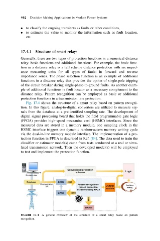
Fig. 17.4 shows the structure of a smart relay based on pattern recogni-
tion. In this figure, analog-to-digital converters are utilized to measure sig-
nals from the database at a preidentified sampling rate. The development of
digital signal processing board that holds the field programmable gate logic
(FPGA) provides high-speed mezzanine card (HSMC) interfaces. Since the
measured data are stored in a memory module, one sampling clock in the
HSMC interface triggers one dynamic random-access memory writing cycle
via the dual-in-line memory module interface. The implementation of a pro-
tection function in FPGA is described in Ref. [84]. The data used to train the
classifier or estimator model(s) came from tests conducted at a real or simu-
lated transmission network. Then the developed model(s) will be employed
to test and implement the protection function.
FIGURE 17.4 A general overview of the structure of a smart relay based on pattern
recognition.