
Page 82 - Defrosting for Air Source Heat Pump
P. 82
74 Defrosting for Air Source Heat Pump
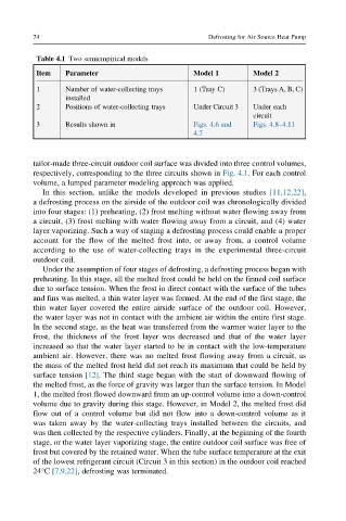
Table 4.1 Two semiempirical models
Item Parameter Model 1 Model 2
1 Number of water-collecting trays 1 (Tray C) 3 (Trays A, B, C)
installed
2 Positions of water-collecting trays Under Circuit 3 Under each
circuit
3 Results shown in Figs. 4.6 and Figs. 4.8–4.11
4.7
tailor-made three-circuit outdoor coil surface was divided into three control volumes,
respectively, corresponding to the three circuits shown in Fig. 4.1. For each control
volume, a lumped parameter modeling approach was applied.
In this section, unlike the models developed in previous studies [11,12,22],
a defrosting process on the airside of the outdoor coil was chronologically divided
into four stages: (1) preheating, (2) frost melting without water flowing away from
a circuit, (3) frost melting with water flowing away from a circuit, and (4) water
layer vaporizing. Such a way of staging a defrosting process could enable a proper
account for the flow of the melted frost into, or away from, a control volume
according to the use of water-collecting trays in the experimental three-circuit
outdoor coil.
Under the assumption of four stages of defrosting, a defrosting process began with
preheating. In this stage, all the melted frost could be held on the finned coil surface
due to surface tension. When the frost in direct contact with the surface of the tubes
and fins was melted, a thin water layer was formed. At the end of the first stage, the
thin water layer covered the entire airside surface of the outdoor coil. However,
the water layer was not in contact with the ambient air within the entire first stage.
In the second stage, as the heat was transferred from the warmer water layer to the
frost, the thickness of the frost layer was decreased and that of the water layer
increased so that the water layer started to be in contact with the low-temperature
ambient air. However, there was no melted frost flowing away from a circuit, as
the mass of the melted frost held did not reach its maximum that could be held by
surface tension [12]. The third stage began with the start of downward flowing of
the melted frost, as the force of gravity was larger than the surface tension. In Model
1, the melted frost flowed downward from an up-control volume into a down-control
volume due to gravity during this stage. However, in Model 2, the melted frost did
flow out of a control volume but did not flow into a down-control volume as it
was taken away by the water-collecting trays installed between the circuits, and
was then collected by the respective cylinders. Finally, at the beginning of the fourth
stage, or the water layer vaporizing stage, the entire outdoor coil surface was free of
frost but covered by the retained water. When the tube surface temperature at the exit
of the lowest refrigerant circuit (Circuit 3 in this section) in the outdoor coil reached
24°C [7,9,22], defrosting was terminated.