
Page 138 - Design and Operation of Heat Exchangers and their Networks
P. 138
126 Design and operation of heat exchangers and their networks
0:5403 0:1541 0:1499
j ¼ 0:6522Re α β
3 ðÞ f f
0:1 (3.290)
α
γ 0:0678 1+5:269 10 5 Re 1:34 0:504 0:456 1:055
β
γ
f 3 ðÞ f f f
Based on CFD calculation, Chennu and Paturu (2011) proposed the fol-
lowing correlations:
α
γ
β
f 2ðÞ ¼ 10:882Re 0:79 0:359 0:284 0:187 300 Re 2ðÞ 800 (3.291)
2 ðÞ f f f
β
γ
α
f 2ðÞ ¼ 2:237Re 0:236 0:347 0:639 0:151 1000 Re 2ðÞ 1500 (3.292)
2 ðÞ f f f
0:9 0:343 0:305 0:538
j ¼ 0:661Re α β γ 300 Re 2ðÞ 800 (3.293)
2 ðÞ f f f
0:396 0:178 0:29 0:403
j ¼ 0:185Re α β γ 1000 Re 2ðÞ 1500 (3.294)
2 ðÞ f f f
Other correlations can also be found in the literature (Mochizuki et al.,
1987; Muzychka and Yovanovich, 2001; Kim et al., 2011; Yang and Li,
2014; Song et al., 2017).
Comparing the previous correlations with the data of Kays and London
(1984), we find that the correlations of Manglik and Bergles (1995),
Eqs. (3.289), (3.290), and those of Wieting (1975), Eqs. (3.268)–(3.271),
have the smallest standard relative deviation.
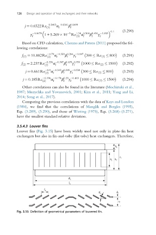
3.5.4.3 Louver fins
Louver fins (Fig. 3.15) have been widely used not only in plate-fin heat
exchangers but also in fin-and-tube (flat tube) heat exchangers. Therefore,
b t
s t
h l h f
B t
l s
l p
q s d f
s f
Fig. 3.15 Definition of geometrical parameters of louvered fin.