
Page 156 - Design and Operation of Heat Exchangers and their Networks
P. 156
Steady-state characteristics of heat exchangers 143
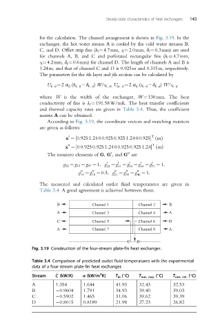
for the calculation. The channel arrangement is shown in Fig. 3.19.In the
exchanger, the hot water stream A is cooled by the cold water streams B,
C, and D. Offset strip fins (h f ¼4.7mm, s f ¼2.0mm, δ f ¼0.3mm) are used
for channels A, B, and C and perforated rectangular fins (h f ¼4.7mm,
s f ¼4.2mm, δ f ¼0.6mm) for channel D. The length of channels A and B is
1.24m, and that of channel C and D is 0.925m and 0.315m, respectively.
The parameters for the ith layer and jth section can be calculated by
U f, ij ¼2 α ij (h f, ij δ f, ij ) W/s f, ij , U p, ij ¼2 α ij (s f, ij δ f, ij ) W/s f, ij
where W is the width of the exchanger, W¼130mm. The heat
conductivity of fins is λ f ¼191.58W/mK. The heat transfer coefficients
and thermal capacity rates are given in Table 3.4. Thus, the coefficient
matrix A can be obtained.
According to Fig. 3.19, the coordinate vectors and matching matrices
are given as follows:
0 T
m
x ¼ 0:925 1:24 00:925 0:925 1:24 00:925½ ðÞ
T
m
00
x ¼ 00:925 0:925 1:24 00:925 0:925 1:24½ ðÞ
The nonzero elements of G, G , and G are
0
00
0
g 12 ¼ g 43 ¼ g 87 ¼ 1, g ¼ g ¼ g ¼ g ¼ g ¼ 1,
0
0
0
0
22 31 53 64 71
g ¼ g ¼ 0:5, g ¼ g ¼ g ¼ 1:
00
00
00
00
00
14 18 21 35 46
The measured and calculated outlet fluid temperatures are given in
Table 3.4. A good agreement is achieved between them.
B Channel 1 Channel 2 B
A Channel 3 Channel 4 A
C Channel 5 Channel 6 D
A Channel 7 Channel 8 A
C D
Fig. 3.19 Construction of the four-stream plate-fin heat exchanger.
Table 3.4 Comparison of predicted outlet fluid temperatures with the experimental
data of a four-stream plate-fin heat exchanger.
2
_
Stream C (kW/K) α (kW/m K) T in (°C) T out, exp. (°C) T out, cal. (°C)
A 1.354 1.644 41.93 32.43 32.53
B 0.9604 1.791 34.93 39.40 39.03
C 0.5902 1.465 31.06 39.62 39.39
D 0.8015 0.8189 21.98 27.23 26.82