
Page 155 - Design and Operation of Heat Exchangers and their Networks
P. 155
142 Design and operation of heat exchangers and their networks
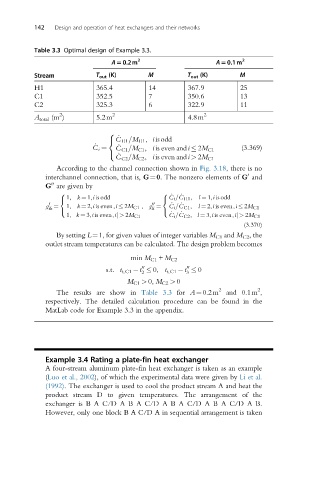
Table 3.3 Optimal design of Example 3.3.
A50.2m 2 A50.1m 2
Stream T out (K) M T out (K) M
H1 365.4 14 367.9 25
C1 352.5 7 350.6 13
C2 325.3 6 322.9 11
2
A total (m ) 5.2m 2 4.8m 2
8
_
C H1 =M H1 , i isodd
<
_ _
C i ¼ C C1 =M C1 , i is even and i 2M C1 (3.369)
: _
C C2 =M C2 , i is even and i > 2M C1
According to the channel connection shown in Fig. 3.18, there is no
interchannel connection, that is, G¼0. The nonzero elements of G and
0
00
G are given by
8 8
1, k ¼ 1,i is odd _ C i = _ C H1 , l ¼ 1,i is odd
< <
0 00
g ¼ 1, k ¼ 2,i is even,i 2M C1 , g ¼ _ C i = _ C C1 , l ¼ 2,i is even,i 2M C1
ik li
: :
1, k ¼ 3,i is even,i| > 2M C1 _ C i = _ C C2 , l ¼ 3,i is even,i| > 2M C1
(3.370)
By setting L¼1, for given values of integer variables M C1 and M C2 , the
outlet stream temperatures can be calculated. The design problem becomes
min M C1 + M C2
00
00
s:t: t t,C1 t 0, t t,C1 t 0
2 3
M C1 > 0, M C2 > 0
2
The results are show in Table 3.3 for A¼0.2m 2 and 0.1m ,
respectively. The detailed calculation procedure can be found in the
MatLab code for Example 3.3 in the appendix.
Example 3.4 Rating a plate-fin heat exchanger
A four-stream aluminum plate-fin heat exchanger is taken as an example
(Luo et al., 2002), of which the experimental data were given by Li et al.
(1992). The exchanger is used to cool the product stream A and heat the
product stream D to given temperatures. The arrangement of the
exchanger is B A C/D A B A C/D A B A C/D A B A C/D A B.
However, only one block B A C/D A in sequential arrangement is taken