
Page 150 - Design and Operation of Heat Exchangers and their Networks
P. 150
138 Design and operation of heat exchangers and their networks
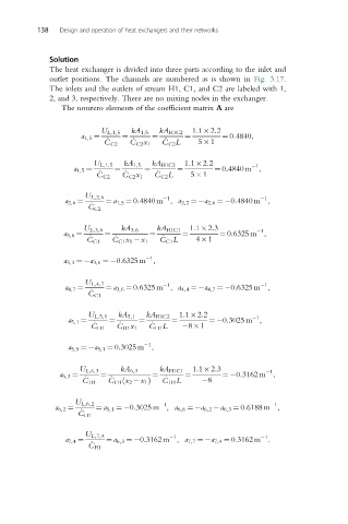
Solution
The heat exchanger is divided into three parts according to the inlet and
outlet positions. The channels are numbered as is shown in Fig. 3.17.
The inlets and the outlets of stream H1, C1, and C2 are labeled with 1,
2, and 3, respectively. There are no mixing nodes in the exchanger.
The nonzero elements of the coefficient matrix A are
U L,1,5 kA 1,5 kA H1C2 1:1 2:2
a 1,5 ¼ _ ¼ _ ¼ _ ¼ ¼ 0:4840,
C C2 C C2 x 1 C C2 L 5 1
1:1 2:2
U L,1,5 kA 1,5 kA H1C2 1
a 1,5 ¼ ¼ ¼ ¼ ¼ 0:4840 m ,
_ C C2 L
_ C C2 _ C C2 x 1 5 1
U L,2,6 1 1
a 2,6 ¼ _ ¼ a 1,5 ¼ 0:4840 m , a 2,2 ¼ a 2,6 ¼ 0:4840 m ,
C C2
1:1 2:3
U L,3,6 kA 3,6 kA H1C1 1
a 3,6 ¼ ¼ ¼ ¼ ¼ 0:6325 m ,
_ C C1 L
_ C C1 _ C C1 x 1 x 1 4 1
1
a 3,3 ¼ a 3,6 ¼ 0:6325 m ,
U L,4,7 1 1
a 4,7 ¼ ¼ a 3,6 ¼ 0:6325 m , a 4,4 ¼ a 4,7 ¼ 0:6325 m ,
_
C C1
1:1 2:2
U L,5,1 kA 5,1 kA H1C2 1
a 5,1 ¼ ¼ ¼ ¼ ¼ 0:3025 m ,
_
_
_
C H1 C H1 x 1 C H1 L 8 1
1
a 5,5 ¼ a 5,1 ¼ 0:3025 m ,
U L,6,3 kA 6,3 kA H1C1 1:1 2:3 1
a 6,3 ¼ _ ¼ _ ¼ _ ¼ ¼ 0:3162 m ,
ð
C H1 C H1 x 2 x 1 Þ C H1 L 8
U L,6,2 1 1
a 6,2 ¼ ¼ a 5,1 ¼ 0:3025 m , a 6,6 ¼ a 6,2 a 6,3 ¼ 0:6188 m ,
_
C H1
U L,7,4 1 1
a 7,4 ¼ ¼ a 6,3 ¼ 0:3162 m , a 7,7 ¼ a 7,4 ¼ 0:3162 m :
_
C H1