
Page 145 - Design and Operation of Heat Exchangers and their Networks
P. 145
Steady-state characteristics of heat exchangers 133
There are two kinds of block arrangements: One is the sequential
arrangement, for example,
i¼1 i¼2 ⋯ i¼n i¼1 i¼2 ⋯ i¼n i¼1 i¼2 ⋯ i¼n
⋯ A B C D A B C D A B C D ⋯
|fflfflfflfflfflfflfflffl{zfflfflfflfflfflfflfflffl} |fflfflfflfflfflfflfflffl{zfflfflfflfflfflfflfflffl} |fflfflfflfflfflfflfflffl{zfflfflfflfflfflfflfflffl}
Block j 1 Block j Block j +1
The other is the symmetrical arrangement, for example,
i¼n i¼n 1 i¼1 i¼1 i¼2 ⋯ i¼n i¼n i¼n 1 i¼1
⋯D C ⋯ A A B C D D C ⋯ A ⋯
|fflfflfflfflfflfflfflfflffl{zfflfflfflfflfflfflfflfflffl} |fflfflfflfflfflfflfflffl{zfflfflfflfflfflfflfflffl} |fflfflfflfflfflfflfflfflffl{zfflfflfflfflfflfflfflfflffl}
Block j 1 Block j Block j +1
For the sequential arrangement of the blocks, the layer number i¼n+1
points to the first layer in the upper block (i¼1), and the layer number i¼0
points to the nth layer in the lower block (i¼n). For the symmetrical
arrangement, the layer number i¼n+1 points to the same layer in the upper
block (i¼n), and the layer number i¼0 points to the same layer in the lower
block (i¼1). The symmetrical arrangement also means that the block is ther-
mally insulated at the upper and lower surfaces. If the whole exchanger
rather than only a block is analyzed, the symmetrical arrangement should
be adopted.
The symmetrical arrangement can also be formed as
…BABCDD CBABCDDCBAB…
For such an arrangement, we can divide layer A into two equal parts, the one
for block j 1 and the other for block j.
The layer arrangement
…BA BCDCBABCDC BAB…
can be treated in a similar way.
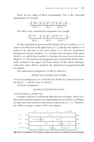
Consider a block in a multistream plate-fin heat exchanger, which has n
layers and is divided along the exchanger length into m sections according to
the inlet and outlet positions of the streams as shown in Fig. 3.16. Therefore,
the whole exchanger consists of M¼mn channels.
j = 1 2 3 j = m = 4
i = 1 x in,1 k = 1 x out,1
i = 2 x out,2 k = 2 x in,2 x out,3 k = 3 x in,3
i = 3 x in,4 k = 4 x out,4 x in,5 k = 5 x out,5
i = n = 4 x out,6 k = 6 x in,6 x out,7 k = N f = 7 x in,7
Fig. 3.16 Arrangement of the streams, layers, and sections in a plate-fin heat exchanger.