
Page 149 - Design and Operation of Heat Exchangers and their Networks
P. 149
Steady-state characteristics of heat exchangers 137
multistream plate-fin heat exchanger, which also contains energy equations
of separating plates and fins, differs from Eq. (3.308). By eliminating the
temperatures of separating plate and fins in the energy equation of fluids,
Luo et al. (2002) transformed the governing equation system into the form
of Eq. (3.308) by expressing the corresponding coefficient matrix A as
Eqs. (3.334), (3.335).
In the following examples, it will be illustrated in detail how to deter-
mine the matrices A, G, G , and G . The examples also show how to
0
00
use the general solution to solve the design problems of multistream heat
exchangers.
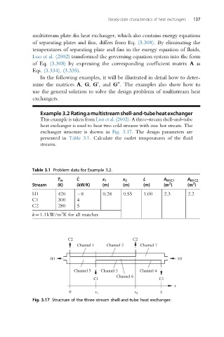
Example 3.2 Ratingamultistreamshell-and-tubeheatexchanger
This example is taken from Luo et al. (2002). A three-stream shell-and-tube
heat exchanger is used to heat two cold streams with one hot stream. The
exchanger structure is shown in Fig. 3.17. The design parameters are
presented in Table 3.1. Calculate the outlet temperatures of the fluid
streams.
Table 3.1 Problem data for Example 3.2.
T in C _ x 1 x 2 L A H1C1 A H1C2
2
2
Stream (K) (kW/K) (m) (m) (m) (m ) (m )
H1 420 8 0.28 0.55 1.00 2.3 2.2
C1 300 4
C2 280 5
2
k¼1.1kW/m K for all matches
C2 C2
Channel 1 Channel 2 Channel 7
H1 H1
Channel 5 Channel 3 Channel 4
Channel 6
C1 C1
x
0 x 1 x 2 L
Fig. 3.17 Structure of the three-stream shell-and-tube heat exchanger.