
Page 154 - Design and Operation of Heat Exchangers and their Networks
P. 154
Steady-state characteristics of heat exchangers 141
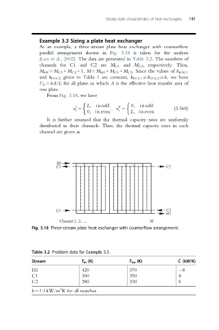
Example 3.3 Sizing a plate heat exchanger
As an example, a three-stream plate heat exchanger with counterflow
parallel arrangement shown in Fig. 3.18 is taken for the analysis
(Luo et al., 2002). The data are presented in Table 3.2. The numbers of
channels for C1 and C2 are M C1 and M C2 , respectively. Thus,
M H1 ¼M C1 +M C2 +1, M¼M H1 +M C1 +M C2 . Since the values of k H1C1
and k H1C2 given in Table 1 are constant, k H1C1 ¼k H1C2 ¼k, we have
U L ¼kA/L for all plates in which A is the effective heat transfer area of
one plate.
From Fig. 3.18, we have
L, i isodd 0, i isodd
0 00
x ¼ , x ¼ (3.368)
i 0, iis even i L, iis even
It is further assumed that the thermal capacity rates are uniformly
distributed in their channels. Thus, the thermal capacity rates in each
channel are given as
H1
C1 C2
C1 C2
H1
Channel 1, 2, ..., M
Fig. 3.18 Three-stream plate heat exchanger with counterflow arrangement.
Table 3.2 Problem data for Example 3.3.
_
Stream T in (K) T tar (K) C (kW/K)
H1 420 370 8
C1 300 350 4
C2 280 320 5
2
k¼1.1kW/m K for all matches