Page 244 - Design and Operation of Heat Exchangers and their Networks
P. 244

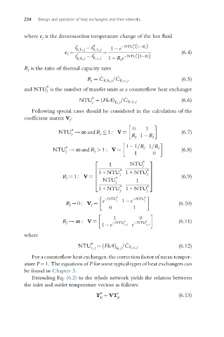
234   Design and operation of heat exchangers and their networks


          where ε j is the dimensionless temperature change of the hot fluid
                                                    ∗
                                                    j ð
                              t 0   t  00   1 e  NTU 1 R jÞ
                              E,h, j  E,h, j
                          ε j ¼          ¼           ∗                 (6.4)
                              t  0   t 0          NTU 1 R jÞ
                                                     j ð
                              E,h, j  E,c, j  1 R j e
          R j is the ratio of thermal capacity rates
                                        _     _
                                   R j ¼ C E,h, j =C E,c, j            (6.5)
                   ∗
          and NTU j is the number of transfer units as a counterflow heat exchanger
                                    ∗            _
                               NTU ¼ FkAð   Þ =C E,h, j                (6.6)
                                    j
                                             E, j
             Following special cases should be considered in the calculation of the
          coefficient matrix V j :

                            ∗                       0    1
                       NTU ! ∞andR j   1 : V ¼                         (6.7)
                            j
                                                    R j 1 R j

                          ∗                      1 1=R j 1=R j
                     NTU ! ∞and R j > 1 : V ¼                          (6.8)
                          j                          1      0
                                     2                  ∗  3
                                           1       NTU  j
                                               ∗
                                     6                    ∗ 7
                                               j
                                                          j
                                     6  1 + NTU 1 + NTU 7
                         R j ¼ 1 : V ¼ 6      ∗            7           (6.9)
                                         NTU         1
                                     4        j            5
                                               ∗
                                       1 + NTU 1 + NTU    ∗ j
                                               j
                                           NTU ∗     NTU ∗
                                        e     j  1 e     j
                          R j ¼ 0 : V j ¼                             (6.10)
                                           0        1

                                             1         0
                         R j ! ∞ : V ¼       NTU ∗   NTU ∗            (6.11)
                                        1 e      c, j  e  c, j
          where
                                    ∗             _
                               NTU      ð                             (6.12)
                                    c, j  ¼ FkAÞ =C E,c, j
                                              E, j
             For a counterflow heat exchanger, the correction factor of mean temper-
          ature F¼1. The equations of F for some typical types of heat exchangers can
          be found in Chapter 3.
             Extending Eq. (6.2) to the whole network yields the relation between
          the inlet and outlet temperature vectors as follows:
                                        00
                                      T ¼ VT  0                       (6.13)
                                        E     E
   239   240   241   242   243   244   245   246   247   248   249