
Page 247 - Design and Operation of Heat Exchangers and their Networks
P. 247
Optimal design of heat exchanger networks 237
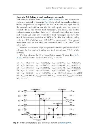
Example 6.1 Rating a heat exchanger network.
This example is taken from Toffolo (2009, Table 6.22).The revisedheat
exchanger network is shown in Fig. 6.1, in which the supply and target
stream temperatures are expressed in bold at the left and right ends of
the network and utilities, and the thermal capacity rates are given in
brackets. It has six process heat exchangers, one mixer, one heater,
and one cooler; therefore, there are 13 channels (excluding the heater
and cooler). All units are counterflow heat exchangers and have the
2
overall heat transfer coefficient of 1kW/m K. The hot and cold utility
costs are 140 $/kW/yr and 10 $/kW/yr, respectively. The annual
0.6
investment costs of the units are calculated with C E ¼1200A $/yr
2
(A in m ).
We want to check the target temperatures of the six process streams and
calculate the hot and cold utility and total annual cost (TAC) of the
network.
We first calculate the 13 13 coefficient matrix V using Eqs. (6.3),
(6.16), which yield its nonzero elements v ij as follows:
E1: v 1,1 ¼0.035474, v 1,2 ¼0.964526, v 2,1 ¼0.823736, v 2,2 ¼0.176264,
E2: v 3,3 ¼0.085687, v 3,4 ¼0.914313, v 4,3 ¼0.839243, v 4,4 ¼0.160757,
E3: v 5,5 ¼0.066855, v 5,6 ¼0.933145, v 6,5 ¼0.846172, v 6,6 ¼0.153828,
E4: v 7,7 ¼0.333332, v 7,8 ¼0.666668, v 8,7 ¼0.887667, v 8,8 ¼0.112333,
E5: v 9,9 ¼0.623621, v 9,10 ¼0.376379, v 10,9 ¼0.837552, v 10,10 ¼0.162448,
E6: v 11,11 ¼0.352057, v 11,12 ¼0.647943, v 12,11 ¼0.432558, v 12,12 ¼0.567442,
M1: v 13,13 ¼1
E1:65.899 m 2 E6:8.61 m 2
500 320
H1
(6)
E2:30.653 m 2
480 380
H2
(4) 320
E3:53.644 m 2
460 360
H3
(6) 300
E5:21.957 m 2
380 360
H4
(20)
E4:39.373 m 2
380 320
H5
(12)
700 M1
660 290 C1
(18)
700 (4.3578) (9.0124)
(6.6167)
Fig. 6.1 Rating example for a heat exchanger network of Toffolo (2009).