
Page 352 - Design and Operation of Heat Exchangers and their Networks
P. 352
338 Design and operation of heat exchangers and their networks
up lumped-distributed parameter models for multistream plate-fin heat
exchanger, in which the coefficients in the transfer functions were deter-
mined by experimental investigation and numerical calculation.
The cell model is first used to predict the temperature distribution and the
mean temperature difference in multipass shell-and-tube exchangers by Gaddis
andSchl€under(1979).Later,RoppoandGanic(1983)andCorreaandMarchetti
(1987) applied it to dynamic simulation of multipass tubular exchangers. By cell
model, the whole apparatus was divided into several elements or cells. Each
elementarycellisconsideredasafictitiousexchanger,and theseelementaryunits
are coupled by the streams involved in the heat transfer process.
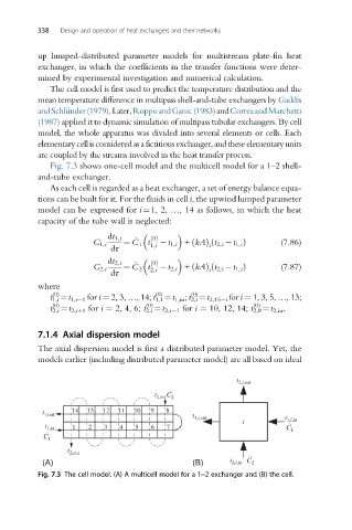
Fig. 7.3 shows one-cell model and the multicell model for a 1–2 shell-
and-tube exchanger.
As each cell is regarded as a heat exchanger, a set of energy balance equa-
tions can be built for it. For the fluids in cell i, the upwind lumped parameter
model can be expressed for i¼1, 2, …, 14 as follows, in which the heat
capacity of the tube wall is neglected:
dt 1,i _ 0 ðÞ
ð
C 1,i ¼ C 1 t 1,i t 1,i + kAð Þ t 2,i t 1,i Þ (7.86)
i
dτ
dt 2,i _ 0 ðÞ
ð
C 2,i ¼ C 2 t 2,i t 2,i + kAð Þ t 2,i t 1,i Þ (7.87)
dτ
i
where
(0)
(0)
(0)
t 1,i ¼t 1,i 1 for i ¼ 2, 3, …,14; t 1,1 ¼t 1,in ; t 2,i ¼t 2,15 i for i ¼ 1, 3, 5, …,13;
(0) (0) (0)
t 2,i ¼t 2,i+1 for i ¼ 2, 4, 6; t 2,i ¼t 2,i 1 for i ¼ 10, 12, 14; t 2,8 ¼t 2,in .
7.1.4 Axial dispersion model
The axial dispersion model is first a distributed parameter model. Yet, the
models earlier (including distributed parameter model) are all based on ideal
t 2,i,out
t 2,in C ˙ 2
t 1,out 14 13 12 11 10 9 8 t
1,i,out
i t 1,i,in
t 1,in 1 2 3 4 5 6 7 C ˙ 1
C ˙
1
t 2,out
(A) (B) t 2,i,in C ˙ 2
Fig. 7.3 The cell model. (A) A multicell model for a 1–2 exchanger and (B) the cell.