
Page 387 - Design and Operation of Heat Exchangers and their Networks
P. 387
370 Design and operation of heat exchangers and their networks
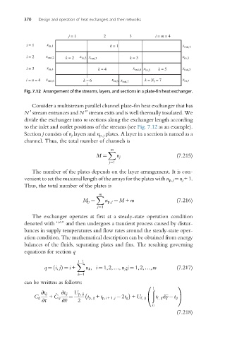
j = 1 2 3 i = m = 4
i = 1 x in,1 k = 1 x out,1
i = 2 x out,2 k = 2 x in,2 x out,3 k = 3 x in,3
i = 3 x in,4 k = 4 x out,4 x in,5 k = 5 x out,5
i = n = 4 x out,6 k = 6 x in,6 x out,7 k = N f = 7 x in,7
Fig. 7.12 Arrangement of the streams, layers, and sections in a plate-fin heat exchanger.
Consider a multistream parallel channel plate-fin heat exchanger that has
00
0
N stream entrances and N stream exits and is well thermally insulated. We
divide the exchanger into m sections along the exchanger length according
to the inlet and outlet positions of the streams (see Fig. 7.12 as an example).
Section j consists of n j layers and n p,j plates. A layer in a section is named as a
channel. Thus, the total number of channels is
m
X
M ¼ n j (7.215)
j¼1
The number of the plates depends on the layer arrangement. It is con-
venient to set the maximal length of the arrays for the plates with n p,j ¼n j +1.
Thus, the total number of the plates is
m
X
M p ¼ n p, j ¼ M + m (7.216)
j¼1
The exchanger operates at first at a steady-state operation condition
denoted with “^” and then undergoes a transient process caused by distur-
bances in supply temperatures and flow rates around the steady-state oper-
ation condition. The mathematical description can be obtained from energy
balances of the fluids, separating plates and fins. The resulting governing
equations for section q
j 1
X
q ¼ i, jðÞ ¼ i + n k , i ¼ 1,2,…, n j ;j ¼ 1,2,…,m (7.217)
k¼1
can be written as follows:
0 1
1
ð
∂t ij _ ∂t ij U p, ij
C ij + C ij ¼ t p, ij + t p,i +1, j 2t ij + U f, ij @ t f, ij dy t ij A
∂τ ∂x 2
0
(7.218)