
Page 386 - Design and Operation of Heat Exchangers and their Networks
P. 386
Dynamic analysis of heat exchangers and their networks 369
Plate 1 Plate 1
Layer 3 Layer 1
Plate 3 Plate 2
Block k+1 Layer 2 Block k+1 Layer 2
Plate 2 Plate 3
Layer 1 Layer 3
Plate 4(1) Plate 4
Layer 3 Layer 3
Plate 3 Plate 3
Block k Layer 2 Block k Layer 2
Plate 2 Plate 2
Layer 1 Layer 1
Plate 1 Plate 1
Layer 3 Layer 1
Plate 3 Plate 2
Block k–1 Layer 2 Block k–1 Layer 2
Plate 2 Plate 3
Layer 1 Layer 3
Plate 1 Plate 4
(A) (B)
Plate 2 Plate 3
Layer 1 Layer 3
Plate 1 Plate 3
Layer 1 Layer 2
Plate 2 Plate 2
Block k+1 Layer 2 Layer 1
Plate 4(3) Plate 2
Layer 3 Block k+1 Layer 2
Plate 3 Plate 4(3)
Layer 2
Block k Layer 3
Plate 2 Plate 3
Layer 1 Block k Layer 2
Plate 1 Plate 2
Layer 1 Layer 1
Plate 2 Plate 1(2)
Block k–1 Layer 2 Block k–1 Layer 2
Plate 3 Plate 3
Layer 3 Layer 3
Plate 3 Plate 3
(C) (D)
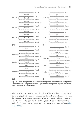
Fig. 7.11 Block arrangements. (A) Sequential arrangement, (B) symmetrical arrangement
I, (C) symmetrical arrangement II, and (D) symmetrical arrangement III (plate n(m)means
plate n and plate m are identical).
solution. It is reasonable because the effect of the axial heat conduction in
fins is negligible. Even so, we can modify the analytical solution by adding
the longitudinal heat conduction area of fins to that of the plates because in a
plate-fin heat exchanger, the effect of longitudinal heat conduction in fins on
outlet fluid temperature response is similar to that in separating plates (Zhu
et al., 2004).