Page 381 - Design and Operation of Heat Exchangers and their Networks
P. 381

364   Design and operation of heat exchangers and their networks


             The system is initially at a nonoperational state with a uniform initial
             temperature t 0 . The nonzero heat transfer parameters are given as

                 U 11 ¼ U 22 ¼ 2W=K, U 31 ¼ U 42 ¼ 12W=K, U 53 ¼ U 64 ¼ 1W=K
                Other values of U ij are zero. The thermal capacities and thermal capacity
             rates are

                  C 1 ¼ C 2 ¼ 0:25 W=K, C 3 ¼ C 4 ¼ C 5 ¼ C 6 ¼ 1W=K,
                                             _
                        _

                  _


                                                   _

                                        _


                                                         _
                    C 1 ¼ C 2 ¼ 0J=K, C 3 ¼ C 4 ¼ 1J=K, C 5 ¼ C 6 ¼ 10 J=K,
                        C w,1 ¼ C w,2 ¼ 1:25 J=K, C w,3 ¼ C w,4 ¼ 1J=K
                The connecting matrices are given as
                 2             3     2    3
                   0 00000             10
                 6  0 00000 7        6  01 7
                 6             7     6    7
                 6 0 00010     7     6 00  7       10 0000
                                              00
                                                                   000
                                   0
             G ¼  6            7 , G ¼  6  7 , G ¼              , G ¼ 0,
                 6 0 00001     7     6 00  7       01 0000
                 6             7     6    7
                   0 00100             00
                 4             5     4    5
                   0 01000             00
                         0               T  00              T
                           ½
                        x ¼ 1 0010 1Š , x ¼ 0 1101 0Š
                                               ½
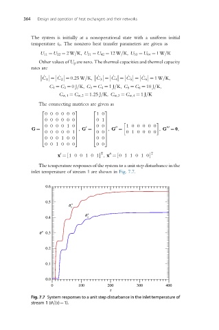
                The temperature responses of the system to a unit step disturbance in the
             inlet temperature of stream 1 are shown in Fig. 7.7.
                   0.6
                   0.5
                            q
                             1
                                  q
                   0.4             2
                q    0.3
                   0.2
                   0.1


                   0.0
                     0          100        200         300        400
                                            t
             Fig. 7.7 System responses to a unit step disturbance in the inlet temperature of
             stream 1 (θ 1 (τ)¼1).
                      0
   376   377   378   379   380   381   382   383   384   385   386