
Page 385 - Design and Operation of Heat Exchangers and their Networks
P. 385
368 Design and operation of heat exchangers and their networks
7.4.1 Mathematical description
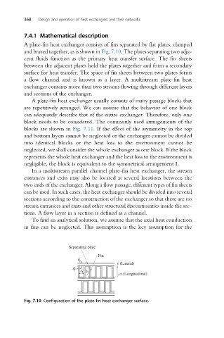
A plate-fin heat exchanger consists of fins separated by flat plates, clamped
and brazed together, as is shown in Fig. 7.10. The plates separating two adja-
cent fluids function as the primary heat transfer surface. The fin sheets
between the adjacent plates hold the plates together and form a secondary
surface for heat transfer. The space of fin sheets between two plates forms
a flow channel and is known as a layer. A multistream plate-fin heat
exchanger contains more than two streams flowing through different layers
and sections of the exchanger.
A plate-fin heat exchanger usually consists of many passage blocks that
are repetitively arranged. We can assume that the behavior of one block
can adequately describe that of the entire exchanger. Therefore, only one
block needs to be considered. The commonly used arrangements of the
blocks are shown in Fig. 7.11. If the effect of the asymmetry in the top
and bottom layers cannot be neglected or the exchanger cannot be divided
into identical blocks or the heat loss to the environment cannot be
neglected, we shall consider the whole exchanger as one block. If the block
represents the whole heat exchanger and the heat loss to the environment is
negligible, the block is equivalent to the symmetrical arrangement I.
In a multistream parallel channel plate-fin heat exchanger, the stream
entrances and exits may also be located at several locations between the
two ends of the exchanger. Along a flow passage, different types of fin sheets
can be used. In such cases, the heat exchanger should be divided into several
sections according to the construction of the exchanger so that there are no
stream entrances and exits and other structural discontinuities inside the sec-
tions. A flow layer in a section is defined as a channel.
To find an analytical solution, we assume that the axial heat conduction
in fins can be neglected. This assumption is the key assumption for the
Separating plate
Fin
d p
y (Lateral)
d f s h f x (Longitudinal)
f
Fig. 7.10 Configuration of the plate-fin heat exchanger surface.