
Page 380 - Design and Operation of Heat Exchangers and their Networks
P. 380
Dynamic analysis of heat exchangers and their networks 363
and the right end is 1. Therefore, the location vectors of inlets and outlets of
channels are
0 T 00 T
½
x ¼ 10 10 , x ¼ 010 1
½
in which the exchanger length is taken as L¼1m. Other parameters used in
the calculation are
_ C 1 ¼ _ C 2 ¼ _ C 3 ¼ _ C 4 ¼ _ C, C 1 = _ C ¼ 0:38s, C 2 = _ C ¼ 0:25s, C 3 = _ C ¼ 0:37s,
C w,1 = _ C ¼ C w,3 = _ C ¼ 0:35s, C w,2 = _ C ¼ 0:30s,
_
_
_
_
_
U 11 =C ¼ U 41 =C ¼ U 33 =C ¼ U 43 =C ¼ 0:8NTU, U 22 =C ¼ U 42 =C _
¼ 0:4NTU,
_
0
0
NTU ¼ U 41 + U 42 + U 43 Þ=C, θ τðÞ ¼ sinτ, θ τðÞ ¼ 0:
ð
1 2
The calculated outlet temperature responses are shown in Fig. 7.5.
Example 7.2 Dynamic responses of two coupled heat
exchanger.
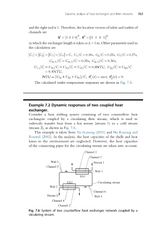
Consider a heat shifting system consisting of two counterflow heat
exchangers coupled by a circulating flow stream, which is used to
indirectly transfer heat from a hot stream (stream 1) to a cold stream
(stream 2), as shown in Fig. 7.6.
This example is taken from Na Ranong (2001) and Na Ranong and
Roetzel (2002). In the analysis, the heat capacities of the shells and heat
losses to the environment are neglected. However, the heat capacities
of the connecting pipes for the circulating stream are taken into account.
Channel 1
Channel 3
Wall 3 Stream 1
Channel 5
Wall 1
EX1
EX2 Circulating stream
Wall 2
Channel 6
Stream 2 Wall 4
Channel 4
Channel 2
Fig. 7.6 System of two counterflow heat exchanger network coupled by a
circulating stream.