Page 379 - Design and Operation of Heat Exchangers and their Networks
P. 379

362   Design and operation of heat exchangers and their networks


                    0.5
                            = 4.0  1.0
                    0.4
                    0.3   NTU   0.5

                    0.2         0.3
                    0.1
                                 0.1
                    q  0.0
                  2
                   -0.1

                   -0.2
                   -0.3
                   -0.4
                   -0.5
                      0   1   2  3   4   5   6  7   8   9  10  11  12
                 (A)                         τ
                    1.0

                    0.8        0.3
                    0.6    NTU = 0.1  0.5
                    0.4         1.0
                                4.0
                    0.2

                    q  0.0
                  1
                   -0.2
                   -0.4
                   -0.6
                   -0.8

                   -1.0
                      0   1   2   3  4   5   6  7   8   9  10  11  12
                 (B)                        τ
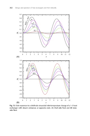
          Fig. 7.5 Exit responses to a shell-side sinusoidal inlet temperature change of a 1–3 heat
          exchanger with stream entrances at opposite ends. (A) Shell-side fluid and (B) tube-
          side fluid.
   374   375   376   377   378   379   380   381   382   383   384