
Page 415 - Design and Operation of Heat Exchangers and their Networks
P. 415
398 Design and operation of heat exchangers and their networks
the measurement is acceptable. The local heat transfer coefficient can then
be determined as
q
α z j ¼ (8.24)
t w,i z j tz j
8.2.2 Test under constant wall temperature
The measurement of heat transfer coefficient under constant wall tempera-
ture condition is usually realized by steam condensation on the other wall
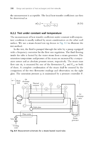
surface. We use a steam-heated test rig shown in Fig. 8.4 to illustrate the
test method.
In the test, the fluid is pumped through the tube by a pump equipped
with a frequency converter for the flow rate regulation. The fluid flowing
inside the tube is heated by the water steam from a steam generator. The
saturation temperature and pressure of the steam are measured by a temper-
ature sensor and an absolute pressure sensor, respectively. The steam mass
flow rate _m h is measured by one of the flowmeters F s,1 and F s,2 or both
of them. A complete condensation of the steam shall be ensured by the
comparison of the two flowmeter readings and observation on the sight
glass. The saturation pressure p s is maintained by a pressure controller P.
Air
Hoch discharge
tank valve Thermal
isolation T s P s
F s,2
F w T 1 T 2
ΔP
Air
discharge
valve
Pump P
F s,1
Sight glass
Plate cooler
~U
Steam
Valve
generator
Cooling
water
Fig. 8.4 Measurement schematic for a steam-heated round tube.