
Page 63 - Design and Operation of Heat Exchangers and their Networks
P. 63
50 Design and operation of heat exchangers and their networks
For rating problems, Eq. (2.109) can be used, in which the apparent
overall heat transfer coefficient can be calculated from the apparent heat
transfer coefficient α d :
1 1 1 1 1 1
¼ + , ¼ + (2.114)
_
_
α d,h A h α h A h C h Pe h α d,c A c α c A c C c Pe c
and can be expressed as
1 1 1 1
¼ + + (2.115)
_
_
k∗A kA C h Pe h C c Pe c
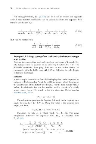
Example 2.7 Sizing a counterflow shell-and-tube heat exchanger
with baffles
Resizing the counterflow shell-and-tube heat exchanger of Example 2.4.
The tubeside flow is assumed to be uniform; therefore, Pe h ¼∞.The
shell-side deviations from plug flow due to the baffles should be
considered, with the baffle space ΔL 0.5m. Calculate the tube length
of the heat exchanger.
Solution
In this example, the deviation from shell-side plug flow can be expressed by
a dispersive Peclet number Pe c of the cold fluid stream, which depends on
the construction of the baffled tube bundle. For the tube bundle with m
baffles, the shell-side flow can be modeled with a cascade of n axially
mixed zones (n¼m+1), which yields the dispersive Peclet number
(Roetzel et al., 2011):
Pe c ¼ 2n ¼ 2 m +1ð Þ
The calculations presented in Example 2.4 result in the required tube
length for plug flow L¼2.701m. Using this value as the assumed tube
length, we have
n L=ΔL ¼ 2:701=0:5 ¼ 5:402
Therefore, we take n¼6, which yields Pe c ¼2n¼12. The mean
temperature difference for dispersive flow Δt m,d is calculated from
Eq. (2.110):
00
t t 00 c t t 0 c t t 00 t t 0
0
00
0
h
h
Δt m,d ¼ h h c c
00
ln t t = t t c 0 Pe h Pe c
0
00
h
c
h
ð 100 70Þ 80 20Þ 100 80 70 20
ð
¼ ¼ 39:11K
½
ln 100 70Þ= 80 20Þ ∞ 12
ð
ð