
Page 219 - Design for Six Sigma a Roadmap for Product Development
P. 219
DFSS Transfer Function and Scorecards 191
functions input/output (this step is a design synthesis step). Inputs
are classified by Phal and Beitz (1988) as information, material, or
energy.
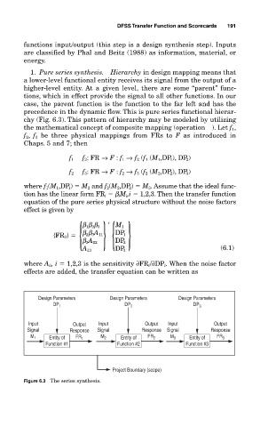
1. Pure series synthesis. Hierarchy in design mapping means that
a lower-level functional entity receives its signal from the output of a
higher-level entity. At a given level, there are some “parent” func-
tions, which in effect provide the signal to all other functions. In our
case, the parent function is the function to the far left and has the
precedence in the dynamic flow. This is pure series functional hierar-
chy (Fig. 6.3). This pattern of hierarchy may be modeled by utilizing
the mathematical concept of composite mapping (operation ●). Let f 1 ,
f 2 , f 3 be three physical mappings from FRs to F as introduced in
Chaps. 5 and 7; then
f 1 ● f 2 :FR → F : f 1 → f 2 (f 1 (M 1 ,DP 1 ), DP 2 )
f 2 ● f 3 :FR → F : f 2 → f 3 (f 2 (M 2 ,DP 2 ), DP 3 )
where f 1 (M 1 ,DP 1 ) M 2 and f 2 (M 2 ,DP 2 ) M 3 . Assume that the ideal func-
tion has the linear form FR i β i M i ,i 1,2,3. Then the transfer function
equation of the pure series physical structure without the noise factors
effect is given by
{ }{ }
′ M 1
β 1β 2β 3
{FR 3} β 2β 3 A 11 DP 1
DP 2
β 3 A 22
A 33 DP 3 (6.1)
where A ii ,i 1,2,3 is the sensitivity ∂FR i /∂DP i . When the noise factor
effects are added, the transfer equation can be written as
Design Parameters Design Parameters Design Parameters
DP 1 DP 2 DP 3
Input Output Input Output Input Output
Signal Response Signal Response Signal Response
M 1 Entity of FR 1 M 2 Entity of FR 2 M 3 Entity of FR 3
Function #1 Function #2 Function #3
Project Boundary (scope)
Figure 6.3 The series synthesis.