
Page 121 - Design of Reinforced Masonry Structures
P. 121
MATERIALS OF MASONRY CONSTRUCTION 3.15
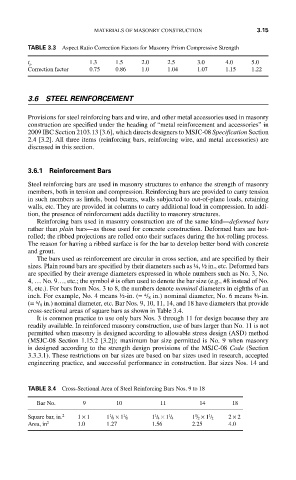
TABLE 3.3 Aspect Ratio Correction Factors for Masonry Prism Compressive Strength
1.3 1.5 2.0 2.5 3.0 4.0 5.0
t p
Correction factor 0.75 0.86 1.0 1.04 1.07 1.15 1.22
3.6 STEEL REINFORCEMENT
Provisions for steel reinforcing bars and wire, and other metal accessories used in masonry
construction are specified under the heading of “metal reinforcement and accessories” in
2009 IBC Section 2103.13 [3.6], which directs designers to MSJC-08 Specification Section
2.4 [3.2]. All three items (reinforcing bars, reinforcing wire, and metal accessories) are
discussed in this section.
3.6.1 Reinforcement Bars
Steel reinforcing bars are used in masonry structures to enhance the strength of masonry
members, both in tension and compression. Reinforcing bars are provided to carry tension
in such members as lintels, bond beams, walls subjected to out-of-plane loads, retaining
walls, etc. They are provided in columns to carry additional load in compression. In addi-
tion, the presence of reinforcement adds ductility to masonry structures.
Reinforcing bars used in masonry construction are of the same kind—deformed bars
rather than plain bars—as those used for concrete construction. Deformed bars are hot-
rolled; the ribbed projections are rolled onto their surfaces during the hot-rolling process.
The reason for having a ribbed surface is for the bar to develop better bond with concrete
and grout.
The bars used as reinforcement are circular in cross section, and are specified by their
sizes. Plain round bars are specified by their diameters such as ¼, ½ in., etc. Deformed bars
are specified by their average diameters expressed in whole numbers such as No. 3, No.
4, … No. 9…, etc.; the symbol # is often used to denote the bar size (e.g., #8 instead of No.
8, etc.). For bars from Nos. 3 to 8, the numbers denote nominal diameters in eighths of an
4
inch. For example, No. 4 means ½-in. (= / 8 in.) nominal diameter, No. 6 means ¾-in.
6
(= / 8 in.) nominal diameter, etc. Bar Nos. 9, 10, 11, 14, and 18 have diameters that provide
cross-sectional areas of square bars as shown in Table 3.4.
It is common practice to use only bars Nos. 3 through 11 for design because they are
readily available. In reinforced masonry construction, use of bars larger than No. 11 is not
permitted when masonry is designed according to allowable stress design (ASD) method
(MSJC-08 Section 1.15.2 [3.2]); maximum bar size permitted is No. 9 when masonry
is designed according to the strength design provisions of the MSJC-08 Code (Section
3.3.3.1). These restrictions on bar sizes are based on bar sizes used in research, accepted
engineering practice, and successful performance in construction. Bar sizes Nos. 14 and
TABLE 3.4 Cross-Sectional Area of Steel Reinforcing Bars Nos. 9 to 18
Bar No. 9 10 11 14 18
1
1
1
1
1
1
Square bar, in. 2 1 × 1 1 / 8 × 1 / 8 1 / 4 × 1 / 4 1 / 2 × 1 / 2 2 × 2
Area, in 2 1.0 1.27 1.56 2.25 4.0