
Page 127 - Design of Reinforced Masonry Structures
P. 127
MATERIALS OF MASONRY CONSTRUCTION 3.21
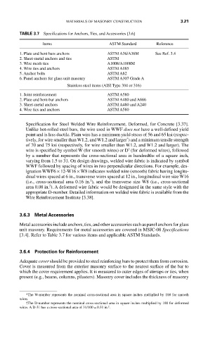
TABLE 3.7 Specifications for Anchors, Ties, and Accessories [3.6]
Items ASTM Standard Reference
1. Plate and bent bars anchors ASTM A36/A36M See Ref. 3.4
2. Sheet-metal anchors and ties ASTM
3. Wire mesh ties A1008/A1008M
4. Wire ties and anchors ASTM A185
5. Anchor bolts ASTM A82
6. Panel anchors for glass unit masonry ASTM A307 Grade A
Stainless steel items (AISI Type 304 or 316)
1. Joint reinforcement ASTM A580
2. Plate and bent-bar anchors ASTM A480 and A666
3. Sheet-metal anchors ASTM A480 and A240
4. Wire ties and anchors ASTM A580
Specification for Steel Welded Wire Reinforcement, Deformed, for Concrete [3.37].
Unlike hot-rolled steel bars, the wire used in WWF does not have a well-defined yield
point and is less ductile. Plain wire has a minimum yield stress of 56 and 65 ksi (respec-
*
tively, for wire smaller than W1.2, and W1.2 and larger ) and a minimum tensile strength
of 70 and 75 ksi (respectively, for wire smaller than W1.2, and W1.2 and larger). The
†
wire is specified by symbol W (for smooth wires) or D (for deformed wires), followed
by a number that represents the cross-sectional area in hundredths of a square inch,
varying from 1.5 to 31. On design drawings, welded wire fabric is indicated by symbol
WWF followed by spacing of wires in two perpendicular directions. For example, des-
ignation WWF6 × 12-W16 × W8 indicates welded wire (smooth) fabric having longitu-
dinal wires spaced at 6 in., transverse wires spaced at 12 in., longitudinal wire size W16
2
(i.e., cross-sectional area 0.16 in. ), and the transverse size W8 (i.e., cross-sectional
2
area 0.08 in. ). A deformed wire fabric would be designated in the same style with the
appropriate D-number. Detailed information on welded wire fabric is available from the
Wire Reinforcement Institute [3.38].
3.6.3 Metal Accessories
Metal accessories include anchors, ties, and other accessories such as panel anchors for glass
unit masonry. Requirements for metal accessories are covered in MSJC-08 Specifications
[3.4]. Refer to Table 3.7 for various items and applicable ASTM Standards.
3.6.4 Protection for Reinforcement
Adequate cover should be provided to steel reinforcing bars to protect them from corrosion.
Cover is measured from the exterior masonry surface to the nearest surface of the bar to
which the cover requirement applies. It is measured to outer edges of stirrups or ties, when
present (e.g., beams, columns, pilasters). Masonry cover includes the thickness of masonry
*The W-number represents the nominal cross-sectional area in square inches multiplied by 100 for smooth
wires.
†The D-number represents the nominal cross-sectional area in square inches multiplied by 100 for deformed
2
wires. A D-31 has a cross-sectional area of 31/100 = 0.31 in. .