
Page 160 - Design of Reinforced Masonry Structures
P. 160
4.24 CHAPTER FOUR
From Eq. (4.37)
08
8
ρ = A s = (. ) = .0 00269
bd (. )(34 )
96
3
From Eq. (4.40)
f (60 )
ω = ρ y = (.00269 ) = .1076
0
0
′ f (. )
15
m
From Eq. (4.43)
φM = φ f bd 2 ω(1 − .625 ω)]
′
0
[
n
m
= .[( . ) .09 15 (963 )(34)) ( . 0 1076 )(1 0− .625 0× .1076 )]
2
= 1508 .3 lb-in. = 1225 69 k-ft
.
Alternatively, we could have determined fk from Table A.13. For r = 0.00269 and
n
′ f = 1500 psi, from interpolation,
m
fk = 103 + (150 − 103)(0.69) = 135.43 psi
n
From Eq. (4.47),
⎛ bd 2 ⎞ ⎛ (. ) ( 2
963 34) ⎞
φM = φk n ⎜ ⎟ = 135 43( . ) ⎜ ⎟ = 125 64 k-ft
.
n ⎠ ⎝ 12 000 ⎠
⎝12 000, 2 ,
The above value φM is the same as obtained in Example 4.2. A check should be
n
made to ensure that reinforcement has yielded, and e ≥ 1.5e as shown in Example 4.2
y
s
(calculations not repeated here).
fM = 125.7 k-ft
n
Example 4.7 Using Eq. (4.43), (a) determine the design flexural strength, φM of
n
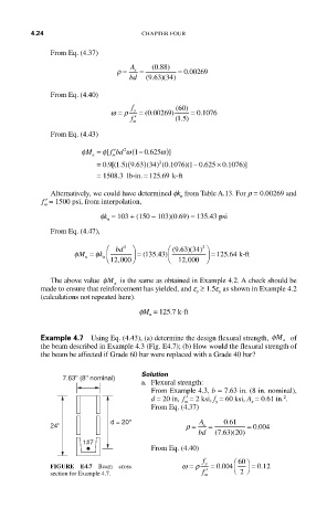
the beam described in Example 4.3 (Fig. E4.7); (b) How would the flexural strength of
the beam be affected if Grade 60 bar were replaced with a Grade 40 bar?
Solution
7.63'' (8'' nominal)
a. Flexural strength:
From Example 4.3, b = 7.63 in. (8 in. nominal),
2
d = 20 in, ′ f = 2 ksi, f = 60 ksi, A = 0.61 in. .
s
y
m
From Eq. (4.37)
d = 20'' A 061
.
24'' ρ = s = = 0 004.
bd (. ) (
763 20)
1#7
From Eq. (4.40)
f ⎛ 60 ⎞
.
FIGURE E4.7 Beam cross ω = ρ y = 0 004 ⎠ = 012.
section for Example 4.7. m ′ f ⎝ 2