
Page 155 - Design of Reinforced Masonry Structures
P. 155
DESIGN OF REINFORCED MASONRY BEAMS 4.19
Verify from Eq. (4.30) that reinforcement has yielded and that e ≥ 1.5e . From Eq. (4.5)
s
y
.
c = a = 457 = 571 .
in
.
.
080 080
.
c 571
.
= = 0 17 < 0 454 (4.30)
.
.
d 34 0
.
Hence, the reinforcement has yielded, and e ≥ 1.5e . Use f = 0.9.
y
s
fM = 0.9(139.55) = 125.6 k-ft > M = 90.0 k-ft OK
u
n
The beam is safe to carry the imposed loads.
(Alternatively, we could have calculated strain in the tension reinforcement from the
strain distribution diagram to verify that e ≥ 1.5e . From the similar triangles of the strain
s
y
distribution diagram,
−
ε dc 34 0 − 5 71
.
.
.
s = = = 4 954
ε mu c 571
.
ε = 4.954 ε = 4.954(0.0025) = 0.0124
s mu u
ε 0 0124
.
>
.
.
s = = = 62 15
ε 0 002
.
y
Therefore, the strain in the tension reinforcement is 6.2 times the yield strain value.
The simplicity of using c/d ratio in lieu of the above calculation to verify that e ≥ 1.5e
s y
should now be obvious.)
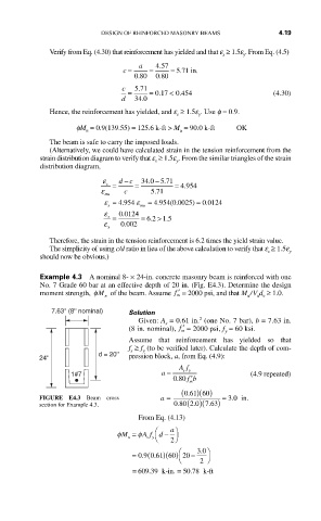
Example 4.3 A nominal 8- × 24-in. concrete masonry beam is reinforced with one
No. 7 Grade 60 bar at an effective depth of 20 in. (Fig. E4.3). Determine the design
moment strength, φM of the beam. Assume ′ f = 2000 psi, and that M / V d ≥ 1.0.
n m u u v
7.63'' (8'' nominal) Solution
2
Given: A = 0.61 in. (one No. 7 bar), b = 7.63 in.
s
(8 in. nominal), ′ f = 2000 psi, f = 60 ksi.
m
y
Assume that reinforcement has yielded so that
f ≥ f (to be verified later). Calculate the depth of com-
s
y
d = 20''
24'' pression block, a, from Eq. (4.9):
Af
080 fb ′ m
1#7 a = sy (4.9 repeated)
.
.
FIGURE E4.3 Beam cross a = (061 60. )( ) = 30 in
.
.
section for Example 4.3. 080 (20. )(763. )
From Eq. (4.13)
φM = φA f ⎛ d − a ⎞
n s y ⎝ ⎠ 2
.
= 09. (061 60 20. )( ) ⎛ − 30 ⎞
⎝ 2 ⎠
.
= 6609 39. k-in . = 50 78 k-ft